Table of Contents
Have you ever visualized a design so vividly that it felt real, only to find the fabrication process complete with friction? The transition from a polished digital model to a tangible, precise object is often trickier than it seems. I’ve faced that challenge, too, watching my perfectly aligned 3D file fall apart when cut and assembled.
That turning point led me to explore the synergy between parametric design and laser cutting. The more I experimented, the clearer it became: digital fabrication isn’t just about tools, it’s about designing with manufacturing in mind from the beginning. Quietly enabling that mindset shift for me was Beegraphy, a design tool that supported the entire process without shouting for attention.
Creating Without Limits: Parametric Design and Laser Cutting in Sync
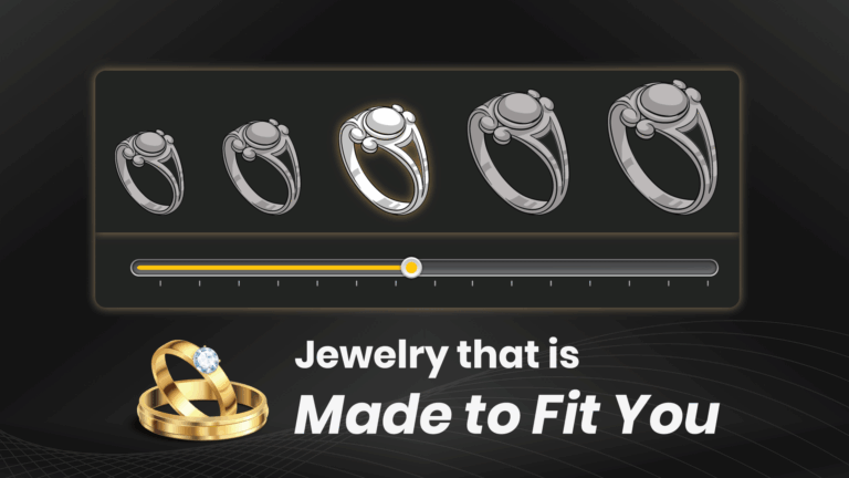
There’s magic in changing a single value in your model, like the width of a panel, and watching the entire design update in real-time. That’s the essence of parametric design. You’re not just creating shapes but rules and logical relationships between components.
Unlike static CAD models, parametric workflows let you control every dimension through variables. You can modify sizes, adjust tolerances, or redesign layouts, all without redrawing anything from scratch.
Now, bring in laser cutting. With its high precision and ability to interpret digital paths down to fractions of a millimetre, it’s the perfect complement. When paired, the parametric design provides innovative geometry, and laser cutting transforms it into reality with exact cuts, tight tolerances, and clean finishes.
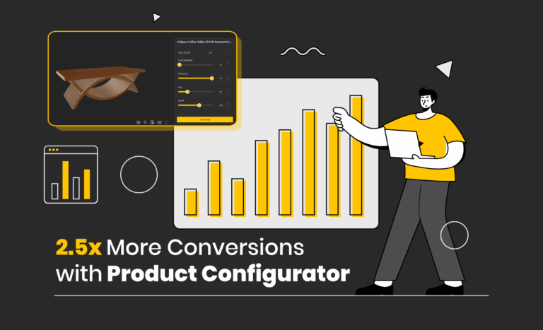
This partnership allows for rapid prototyping, design iteration, and customized manufacturing, all while maximizing efficiency and minimizing material waste.
Laying the Groundwork: Smart Parametric Design for Laser Cutting
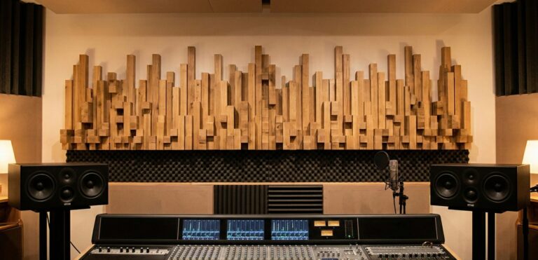
Before the laser ever fires up, successful fabrication starts with a good understanding of your materials and their behaviour under heat and precision cutting.
Choosing Your Canvas: Materials Matter
Your material is more than just a medium, it’s part of the design. Each reacts differently under a laser cutter. Acrylic offers precise, polished cuts but is prone to brittleness and fumes. Plywood is strong and budget-friendly but may contain internal voids. MDF, while affordable and consistent, is dusty and less structurally sound.
Different laser-cutting machines handle these materials in varying ways. A 50W CO₂ laser can easily handle 10mm plywood, while a 5W diode laser might only manage 3mm of birch plywood. Understanding your machine’s capabilities, and linking that understanding to your parametric design, ensures a better outcome.
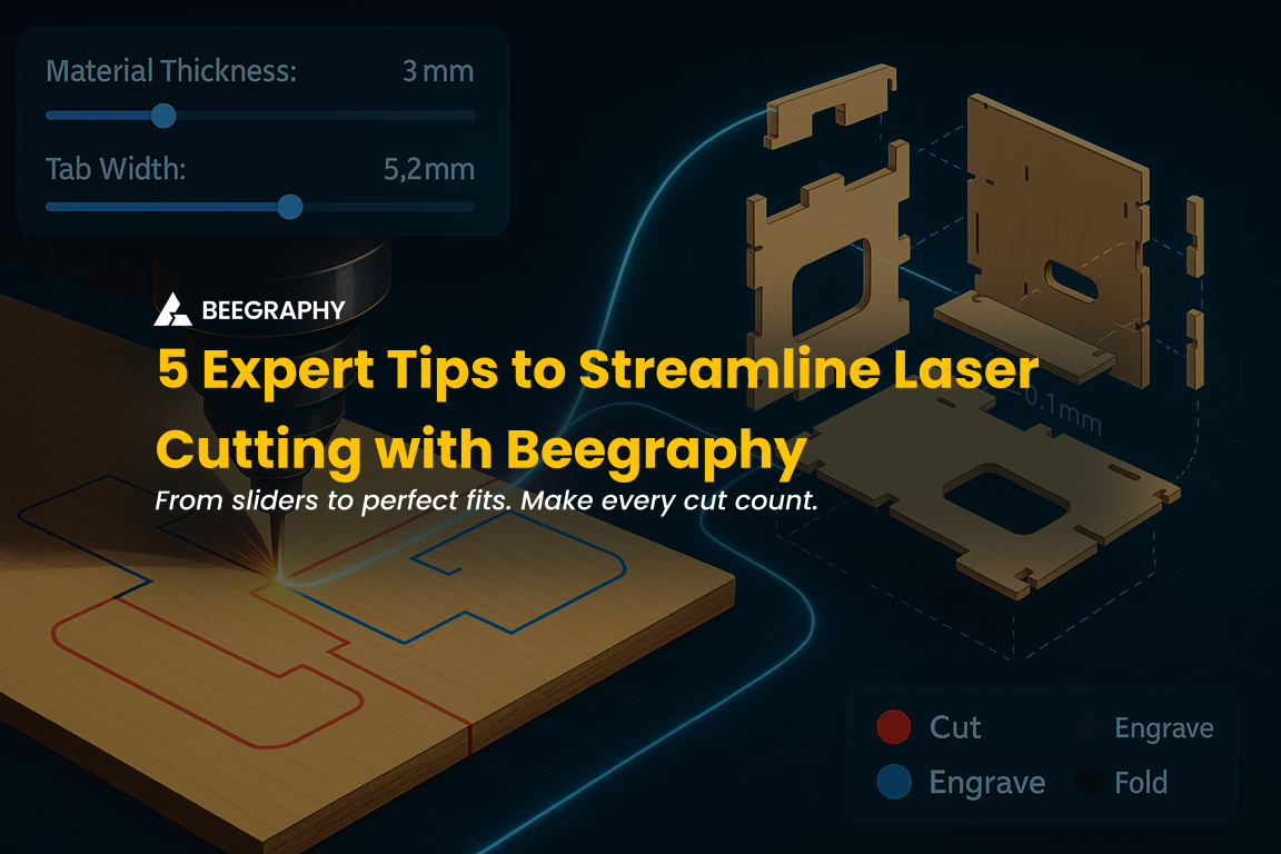
Beegraphy lets you define material thickness as a parameter. That means you can switch between material types or sizes, and your tab sizes, slot depths, and joint tolerances update automatically. No manual redrawing is required.
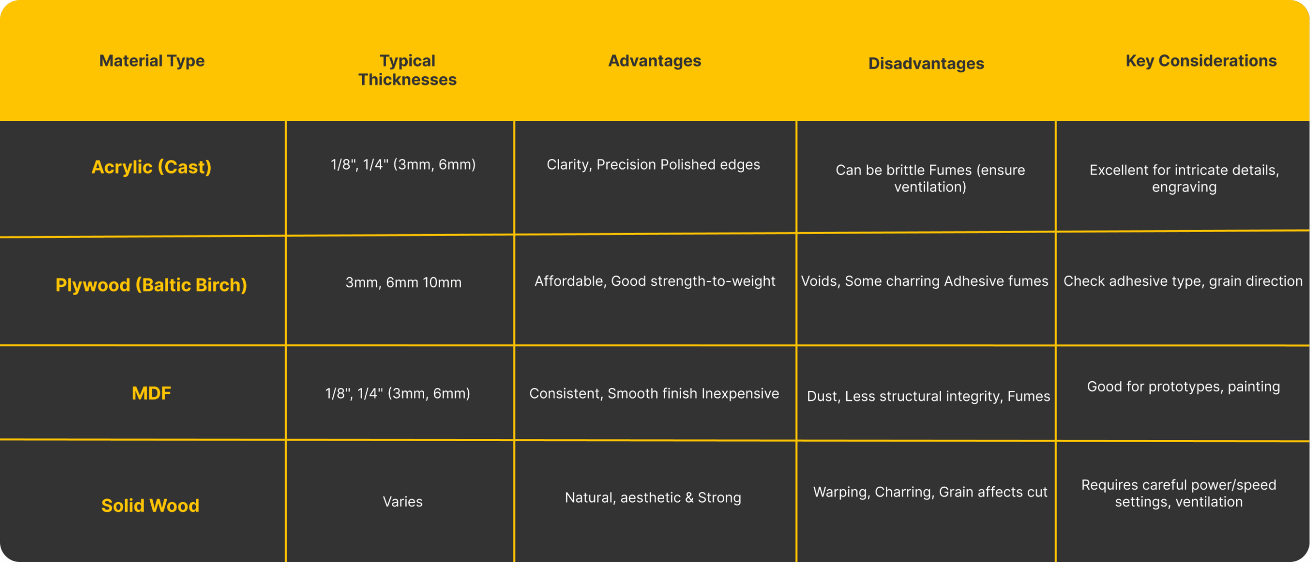
Material guide for laser cutting; compare thicknesses, pros, cons, and key design notes.
The Art of the Perfect Fit: Kerf and Joint Tolerances
One of the first lessons I learned in laser cutting was that the kerf matters. The kerf is the width of material removed by the laser beam, often between 0.1 mm and 0.5 mm, depending on the material and laser type. Ignoring the kerf can lead to joints that are either too tight or too loose.
By incorporating kerf as a variable in my parametric model, I could precisely adjust slot sizes, tab lengths, and clearances. Beegraphy’s slider inputs made testing and tweaking these tolerances easy.
Even small features, like fillets or corner chamfers, can affect assembly. With parametric logic, those micro-adjustments become scalable and repeatable.
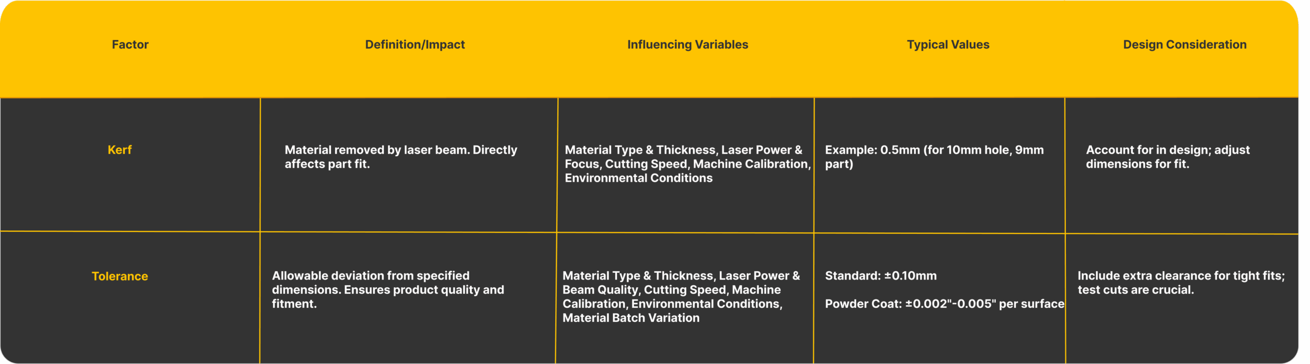
Understanding kerf and tolerance is essential in parametric design for laser cutting; these factors directly impact part fit, precision, and assembly success.
Think Modular: Design for Flat-Pack Perfection
Flat-pack systems aren’t just cost-effective, they’re smart. Designing modular components means you can manufacture, ship, and assemble parts more efficiently. Think IKEA, but personalized.
Parametric design allows one base model to create a range of sizes or styles. I made a shelf that scaled from 300mm to 900mm by changing a value. The rest, slot spacing, panel size, and joint tolerances, are updated automatically.
This kind of agile design works beautifully with laser cutting. You’re working from flat sheets; every component can be exported cleanly. With Beegraphy’s input sliders, updating variations was quick, and the output was fabrication-ready in minutes.
Parametric Logic: Building Smart Components
One of parametric design’s strengths is its ability to solve manufacturing problems before they occur. I began to define relationships that tied joint sizes to material thickness and kerf. I even automated part naming to aid in assembly.
Using Beegraphy’s node-based editor, I could visualize how these relationships functioned and adjust them without writing complex code. This helped me shift my thinking away from just drawing components to engineering complete systems.
From Parametric Design to Precision Cuts: How Beegraphy Streamlines Fabrication
I wasn’t searching for an all-in-one solution when I began integrating parametric design into my process. I just needed a tool to build logic into my models and translate them efficiently for laser cutting. That’s where Beegraphy naturally came in.
Beegraphy’s browser-based platform didn’t require heavy installations. Its intuitive Configurator Mode, driven by sliders for input values, helped me create adjustable, reusable models with ease. Whether it was resizing a frame or adjusting the material thickness, I could instantly see how changes impacted every dependent part.
The platform’s DXF export feature truly helped in laser fabrication. It automatically generated layered files with categorized geometry, such as “cut lines,” “engraving details,” and “fold marks,” streamlining the transfer to the laser software. The built-in Nesting Node was a quiet hero, optimizing material usage by efficiently arranging parts on a sheet, especially crucial in flat-pack design.
Beegraphy became the backbone of my workflow without trying to be the centrepiece, enabling my designs to move seamlessly from digital to physical.
How Beegraphy Applies the 5 Essential Tips for Laser Cutting
After refining dozens of prototypes and adjusting countless parametric sliders, I distilled the workflow into five core strategies. These aren’t just technical tricks , they’re foundational methods that turn good designs into production-ready outputs. If you’re looking to reduce friction, cut waste, and speed up fabrication, here’s where to focus your attention:
1. Structure with Purpose: From Design Logic to Fabrication Script
In Beegraphy, your design is more than just geometry, it’s an intelligent system. Start by building a clear parametric script that generates the essential profiles your laser cutter needs. For example, use nodes to create 2D slices from 3D components, then orient them precisely on the XY plane, which aligns with the laser’s operational surface.
Next, integrate Beegraphy’s Nesting plugin to lay out components efficiently across a virtual material sheet, such as 1200×2400mm plywood. You’ll not only save space but also reduce offcuts and material waste. For joinery-based designs, embed logic to add notches, tabs, or finger joints, these can be parameter-driven and adjusted live, ensuring consistent results at any scale.
Pro tip: Use stream filters and toggles to shift between modeling and fabrication views, this keeps your logic clean and responsive without reworking the script.
Want to see this in action? Watch our YouTube video to explore the full scripting workflow in Beegraphy.
2. Master Layer Control: Assign Laser Operations with Color Precision
Every laser cutter interprets line colors as commands , cut, engrave, score, or ignore. Beegraphy’s Layer Management System allows you to program those commands visually and consistently across all components. Assign RGB values to each type of operation, ensuring predictable machine behavior across multiple jobs or material types.
Here’s how the color-to-function mapping typically works:
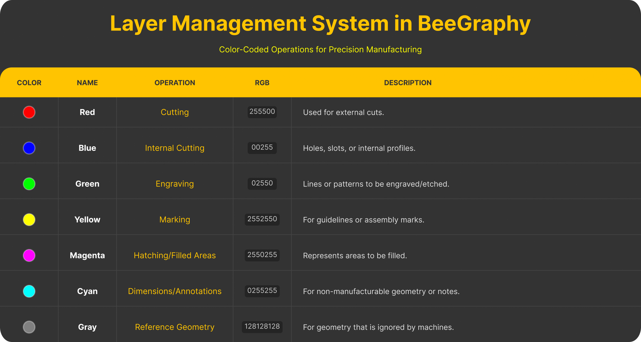
BeeGraphy’s layer system maps laser actions to colors for precise, organized fabrication.
What’s powerful here is not just the visual order but the control you gain. You can calibrate laser intensity, speed, focus, and even assist gas on a per-layer basis , adapting to materials like acrylic, MDF, or cardboard without switching software or manually reassigning operations.
3. Parameterize for Flexibility: One Model, Endless Configurations
Traditional workflows often involve duplicating files for each variation, a wider shelf, a deeper box, a different slot size. Beegraphy removes this inefficiency. Through its parametric configurator, you define your model once and control its behavior with intuitive sliders and input fields.
This system allows real-time updates for:
- Dimensions (length, width, height)
- Spacing, pattern density, repetition
- Custom values like kerf, curvature, hole radius, or join tolerance
The result is a live model that scales across products and applications, modular furniture, lighting systems, packaging templates, or signage, without redrawing or rebuilding anything. Whether you’re adjusting for new hardware or testing proportions, it’s as simple as sliding a control.
BeeGraphy’s parametric configurator enables real-time design adjustments: resize, tweak, and export variations instantly from a single model.
4. Validate Visually: Real-Time Preview for Error-Free Output
Even with logic-driven models, human error can creep in, overlapping paths, wrong layer assignments, unjoined curves. Beegraphy solves this with its real-time 2D and 3D preview environment. As you adjust values or reconfigure components, you get immediate visual feedback on how those changes affect geometry and layer mapping.
This preview process is crucial for:
- Identifying open or duplicate paths.
- Verifying correct layer colors and their associated operations.
- Checking dimensions and tolerances visually before export.
It’s your built-in QA check, helping catch errors before they become wasted material or miscut components. This saves time and cost, especially for batch jobs or commercial fabrication.
By integrating these five strategies into your process, you’re not just improving speed or aesthetics, you’re creating a manufacturing-aware design system. Whether you’re fabricating one prototype or scaling into production, Beegraphy provides the clarity, control, and flexibility to take your laser cutting workflow to the next level.
BeeGraphy’s real-time 3D preview helps validate designs visually: spot errors, confirm settings, and ensure fabrication accuracy before exporting.
5. Export with Confidence: Generate Clean, Cut-Ready DXF Files
Once your model is finalized, the next step is exporting it into a format your laser cutter can interpret accurately, and that means DXF. Beegraphy includes direct DXF export as part of the design workflow, ensuring all geometry, layers, and curve types are ready for fabrication.
Each exported file includes:
- Layered geometry with accurate color and line-type assignment
- Flattened curves aligned to XY
- Polylines and paths optimized for machine readability
There’s no need for post-processing or third-party conversion. Need to tweak the design? Change a value, re-export the DXF, and you’re ready to go again, saving hours during iteration cycles and ensuring precision at every stage.
BeeGraphy’s DXF export generates clean, fabrication-ready files, organized by layer, flattened to XY, and optimized for laser cutting precision.
Common Pitfalls to Avoid
If you’re starting with parametric design and laser cutting, watch out for these:
- Forgetting to match units (mm vs in)
- Exporting curves instead of polylines
- Leaving open or overlapping paths
- Mislabeling layers or colors for laser operations
Good habits and the proper tool setup can make all the difference.
Your Journey from Concept to Creation
Moving from screen to reality isn’t just about hitting “export.” It’s about designing with fabrication in mind, building flexible systems, and refining through iteration.
Parametric design gives you the freedom to think in systems. Laser cutting delivers the precision to make those systems real. And tools like Beegraphy quietly enable that connection, without taking over.
So, next time you dream up a design, build it smart, test it fast, and make it real. True fabrication magic happens when your digital model aligns perfectly with the material world.
Ready to turn your ideas into precision-cut reality? Start building smarter with Beegraphy today.