Table of Contents
The BeeGraphy Computational Design Awards 2026 is coming out soon and we invite designers to pre-register for the competition and focus on the projects participants can create. With several categories to participate in, the awards encourage system-driven thinking, where logic, structure, and real-world application matter as much as visual impact. One of these categories is Facade Systems, which pushes designers to treat facades as functional, buildable systems rather than static patterns.
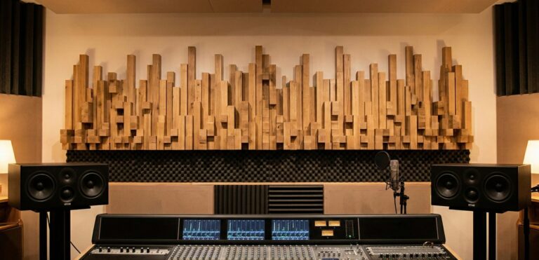
This blog focuses on that Facade Systems category. Instead of designing a purely expressive surface, the goal here is to explore how a facade can be controlled, repeated, varied, and eventually fabricated. The project looks at a coin-based facade made of circular panels arranged in a grid, where movement and variation are driven by a simple wave logic across the surface.
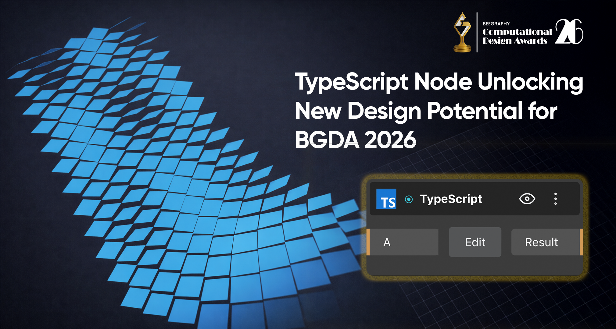
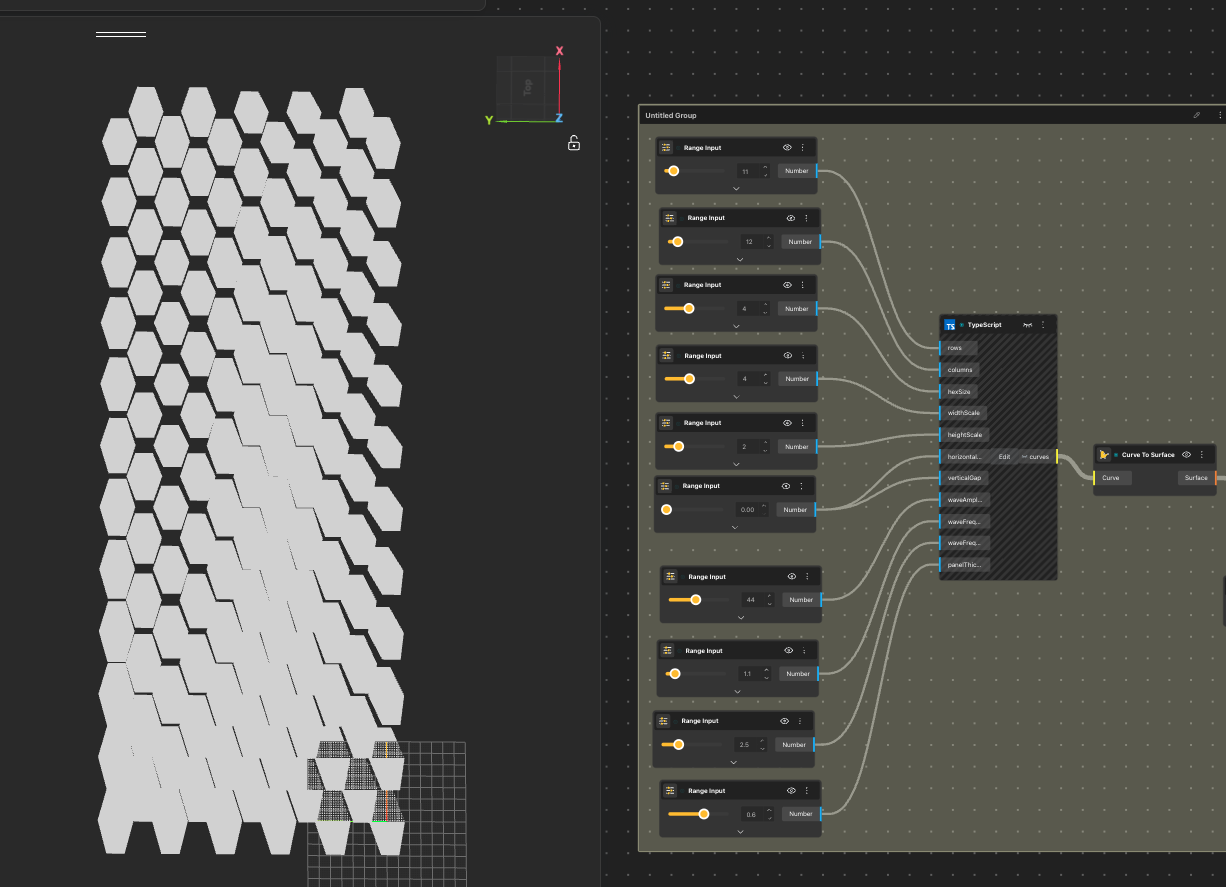
To build this system, I used the TypeScript node in BeeGraphy. So this is not a project about complex scripting or visual effects. It is about using BeeGraphy’s tools to design a facade as a system, one that is understandable, repeatable, and fabrication-ready, for the Facade Systems category of the BeeGraphy Computational Design Awards 2026.

Why a Facade System Instead of a Single Form?
The emphasis on a facade system was not driven by a particular geometry or visual language. The coin facade facade shown in the image was not selected for aesthetic or symbolic reasons. It is the result of an investigation into various kinetic facade systems developed on different geometries and structural logics. The intention was not to develop a particular facade but to examine how facade systems can be developed as computational processes.
Facades are an element of architecture that requires repetition, variation, and constructability. As elements of a larger system, facades are well-suited to parametric design.
Each facade investigation became a different version of the same system logic rather than a unique design, some used diamonds instead of circles, some used squares. The coin facade is one of the results of this investigation, not the end goal. The system itself, a framework that can produce different geometries and remain structurally sound and fabrication-ready, remains the same.
Understanding the Facade as a Rule-Based Rotational Panel System
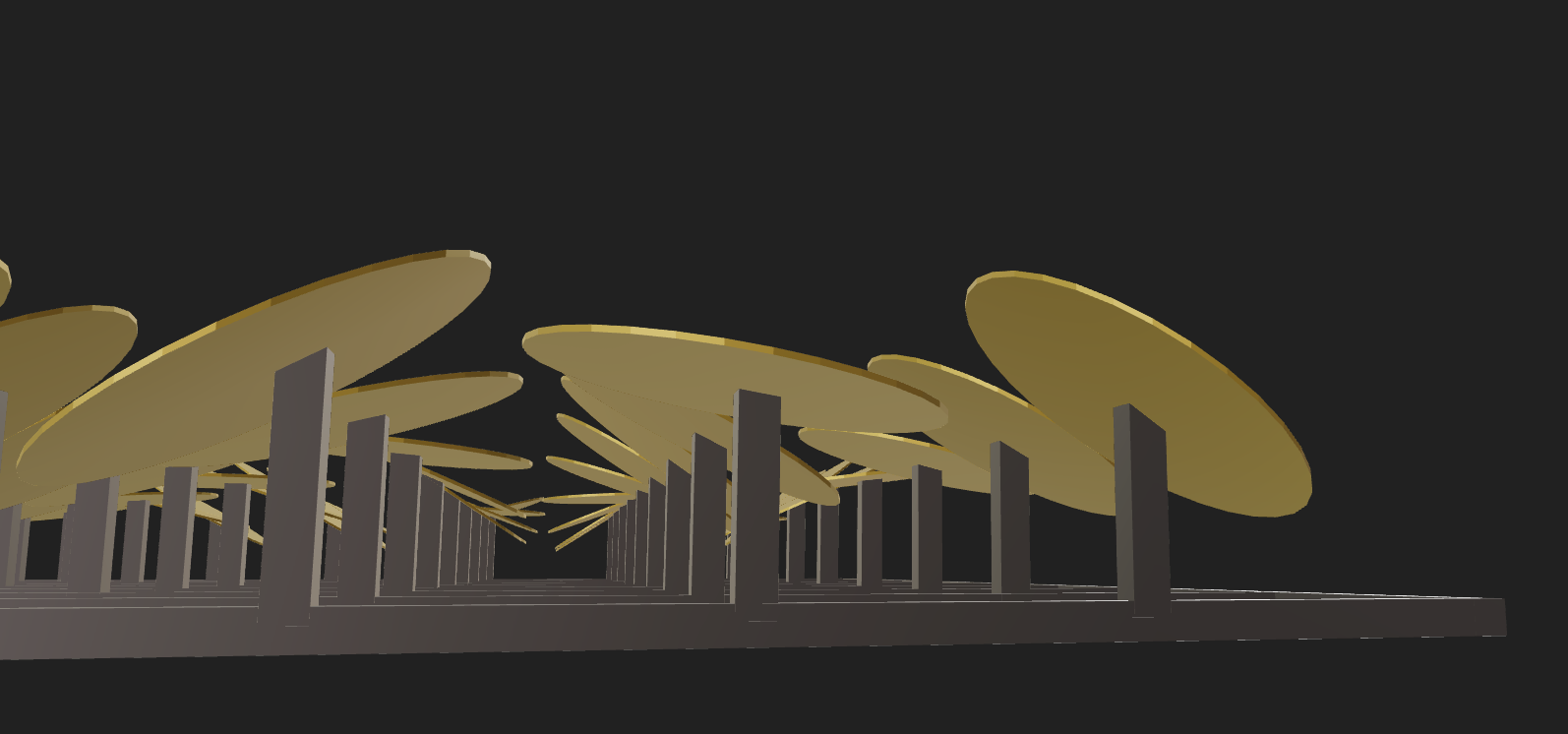
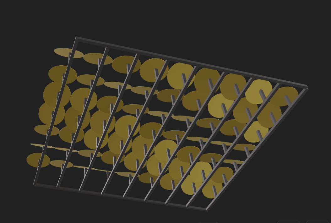
This facade is intended to be a rule-based panel system, structured on a rigid grid system. It is a static system, where variation is achieved by the assigned orientation of circular panels, not by movement. The panels are placed on vertical supports extending from a rectangular framework, achieving controlled depth while retaining modularity and geometric simplicity.
The grid determines the placement of each panel and achieves a repetitive spatial rhythm throughout the facade. Vertical supports are used to translate two-dimensional logic into three-dimensional structure, distinguishing the framework from the surface.
Each panel is assigned a fixed rotational value about its local axis according to a parametric rule applied throughout the grid. From the front, the facade appears as a wave pattern. From an angled perspective, depth and variation are achieved by orientation change.
After the basic system was developed, the same principles could be applied to other shapes. The uniqueness of this facade is its structure, which is focused on fabrication and will be discussed in the next sections.
From Visual Output to Fabrication Logic: Exploration Stage
At a certain point in the process, the facade stopped being just a visual model and started behaving like a system that needed to be understood in terms of making. Instead of asking whether the facade looked interesting, I began to question whether it actually made sense as something that could be produced, assembled, and scaled.
What made this possible was the parametric nature of the system. Because the facade was driven by logic rather than manual modeling, every design decision could be traced back to a rule. This made it easier to rethink the model from a fabrication perspective instead of redesigning it visually.
Some key questions started guiding the process:
-
Can each panel exist as an independent physical part?
-
Can the geometry be flattened into 2D profiles for laser cutting?
-
Are the distances and rotations within realistic fabrication tolerances?
-
Can the system be scaled without breaking its structural logic?
-
Does the grid actually support assembly, or is it just visual?
Instead of treating fabrication as a final step, it became part of the design logic itself. Small changes in parameters immediately revealed their impact on constructability, which made the model feel less speculative and more grounded.
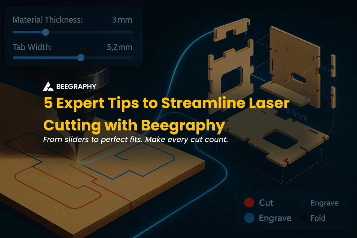
Decoding the Geometry for Laser Cutting
When I started preparing the facade for laser cutting, I realized that the most difficult part was not designing the system, but undoing it. The facade was built on rotations and spatial transformations, which worked naturally in three dimensions, but fabrication demanded a completely different logic. Everything had to be translated into a flat and precise geometric language.
Step 1: Flattening the panels onto the XY plane
The first challenge was removing all rotations from the panels. Each circular element had its own orientation in space, and converting these into planar shapes required stripping away transformations without losing geometric accuracy. Flattening the system was not a straightforward export process. It felt more like decoding the model, where spatial complexity had to be systematically reduced into measurable outlines.
The XY plane of the panels was generated using bounding box alignment and difference boolean logic, allowing the rotated geometries to be projected into clean 2D profiles while preserving their dimensional relationships.
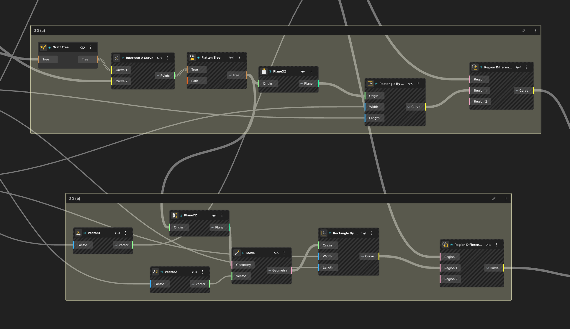
Step 2: Extracting precise outlines for the vertical support bars
Once the panels were resolved, the focus shifted to the vertical support bars. In the 3D model, these bars were positioned at an angle, which made them visually coherent but geometrically complex. To derive accurate laser-cut profiles, I generated bounding boxes for each bar and used boolean operations to carve out their exact outlines. This ensured that the extracted geometry was not approximate, but fabrication-ready.
Step 3: Repeating the logic for horizontal support bars
The same process was then applied to the horizontal bars. Although they appeared simpler in the 3D model, they still carried spatial transformations that needed to be neutralized. By applying the same bounding box and boolean logic, I was able to extract clean, planar curves for these elements as well. At this stage, the facade began to transform from a spatial system into a complete set of 2D components.
Step 4: Optimizing material usage through nesting
The final step was not about geometry, but efficiency. Using the nesting node, I organized all extracted curves to manage spacing between elements for laser cutting. The goal was to minimize material waste while maintaining safe distances between parts. This step revealed another layer of computational design, where optimization became as important as form.
Generating Multiple Facade Variations from a Single Logic
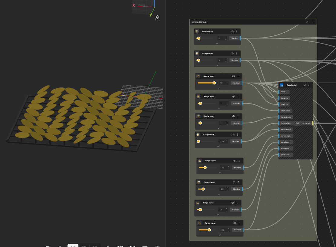
Once the facade system and fabrication logic were established, the focus shifted to variation. Instead of redesigning the facade repeatedly, I explored how different architectural outcomes could emerge from the same computational framework.
By adjusting parameters such as grid density, panel spacing, and rotation intensity, the system produced multiple facade configurations without changing its core structure. Each variation appeared visually distinct, yet all of them were rooted in the same logic. This made it clear that the primary design was not a single facade, but the system that generated it.
Importantly, variation did not compromise fabrication logic. Because the model was parametric, geometric changes automatically respected constraints defined earlier. Panels remained suitable for laser cutting, and structural relationships stayed consistent across versions. Through this process, the facade evolved from a single design into a generative framework. The project demonstrated how a rule-based system can produce multiple, fabrication-aware architectural possibilities without losing coherence or constructability.
Why This Approach Matters for BGDA 2026
This project was developed as a reference example for the Facade Systems category of the BeeGraphy Computational Design Awards 2026.
The relevance of this approach lies in its dual outcome. The system generates visually legible architectural surfaces while simultaneously exposing the decision-making process behind them, from parameter definition to laser-cut preparation. This makes the logic of the design explicit rather than hidden behind form.
By aligning computational structure with fabrication reasoning, the facade moves beyond an aesthetic proposal. It demonstrates how scripting can be used to organize, test, and translate design intent into constructible systems. In doing so, the project reflects a broader shift in computational design, where the intelligence of a system is valued as much as the form it produces.
Creating the model using typescript: Check out the youtube video or the typescript tutorial blog before we move forward
// ===== KINETIC COIN GRID WITH WAVE =====
type CoinGridInPorts = {
  rows: Value<number>;
  columns: Value<number>;
  hexSize: Value<number>;
  widthScale: Value<number>;
  heightScale: Value<number>;
  horizontalGap: Value<number>;
  verticalGap: Value<number>;
  waveAmplitude: Value<number>;
  waveFrequencyX: Value<number>;
  waveFrequencyY: Value<number>;
  panelThickness: Value<number>;
};

async ({
  rows: rowsPort,
  columns: columnsPort,
  hexSize: hexSizePort,
  widthScale: widthScalePort,
  heightScale: heightScalePort,
  horizontalGap: horizontalGapPort,
  verticalGap: verticalGapPort,
  waveAmplitude: waveAmplitudePort,
  waveFrequencyX: waveFrequencyXPort,
  waveFrequencyY: waveFrequencyYPort,
  panelThickness: panelThicknessPort
}: CoinGridInPorts) => {

  const rows = Math.floor(rowsPort.value);
  const columns = Math.floor(columnsPort.value);
  const coinRadius = hexSizePort.value;
  const horizontalGap = horizontalGapPort.value;
  const verticalGap = verticalGapPort.value;
  const maxRotation = waveAmplitudePort.value * (Math.PI / 180);
  const freqX = waveFrequencyXPort.value;
  const freqY = waveFrequencyYPort.value;

  const horizontalSpacing = (coinRadius * 2) + horizontalGap;
  const verticalSpacing = (coinRadius * 2) + verticalGap;

  const circleSegments = 32;
  const allCurves: any[] = [];

  for (let row = 0; row < rows; row++) {
    for (let col = 0; col < columns; col++) {

      const centerX = col * horizontalSpacing;
      const centerY = row * verticalSpacing;

      const normalizedX = col / (columns - 1 || 1);
      const normalizedY = row / (rows - 1 || 1);
      const waveValue =
        Math.sin(normalizedX * Math.PI * freqX + normalizedY * Math.PI * freqY) * 0.5 + 0.5;

      const rotationAngle = maxRotation * (waveValue * 2 - 1);

      const circlePoints = [];
      for (let i = 0; i < circleSegments; i++) {
        const angle = (Math.PI * 2 * i) / circleSegments;

        const localX = coinRadius * Math.cos(angle);
        const localY = coinRadius * Math.sin(angle);
        const localZ = 0;

        const rotatedX = localX * Math.cos(rotationAngle) + localZ * Math.sin(rotationAngle);
        const rotatedZ = -localX * Math.sin(rotationAngle) + localZ * Math.cos(rotationAngle);

        const x = centerX + rotatedX;
        const y = centerY + localY;
        const z = rotatedZ;

        circlePoints.push(new Vector([x, y, z]));
      }

      const coin = await CurveBuilder.polyline(circlePoints, true);
      allCurves.push({
        type: Type.Curve,
        value: coin,
        meta: { color: "#00aaff" }
      });
    }
  }

  return { curves: allCurves };
};
Conclusion
TypeScript in BeeGraphy is not simply an advanced feature or a technical shortcut. It represents a deeper shift in how designers approach creation. When designers move beyond predefined nodes and begin to write logic, they stop designing isolated forms and start constructing systems that can evolve, adapt, and generate meaning.
For the BeeGraphy Design Awards, this shift is especially significant. In a context where visual sophistication is increasingly accessible, what truly differentiates a project is not how complex it looks, but how intelligently it is structured. TypeScript enables designers to articulate their ideas through rules, relationships, and behaviors, making their work not only visually compelling but conceptually rigorous.
As BeeGraphy continues to expand the boundaries between visual tools and code, TypeScript nodes offer designers a powerful way to participate in this evolution. For those aiming to create impactful submissions for the BeeGraphy Design Awards 2026, learning to design with logic is no longer optional. It is a step toward a more intentional, scalable, and future-oriented form of design.
Ultimately, the question is no longer what designers can make with BeeGraphy, but what kinds of systems they are willing to imagine.