Table of Contents
Designers usually rely on slicers and external CAM tools to convert geometry into G-code. BeeGraphy changes this by allowing complete G-code creation inside its visual node environment. This gives designers full control over toolpaths without leaving their browser.
In this guide, you will learn how to take a surface, slice it, sample points, and convert those points into ready to use G-code. The process stays entirely inside BeeGraphy, which makes it ideal for procedural modeling and custom fabrication workflows.
1. Preparing the Surface
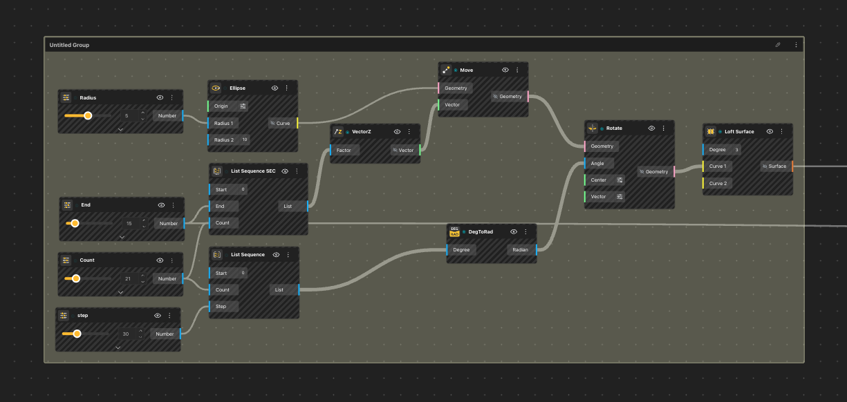
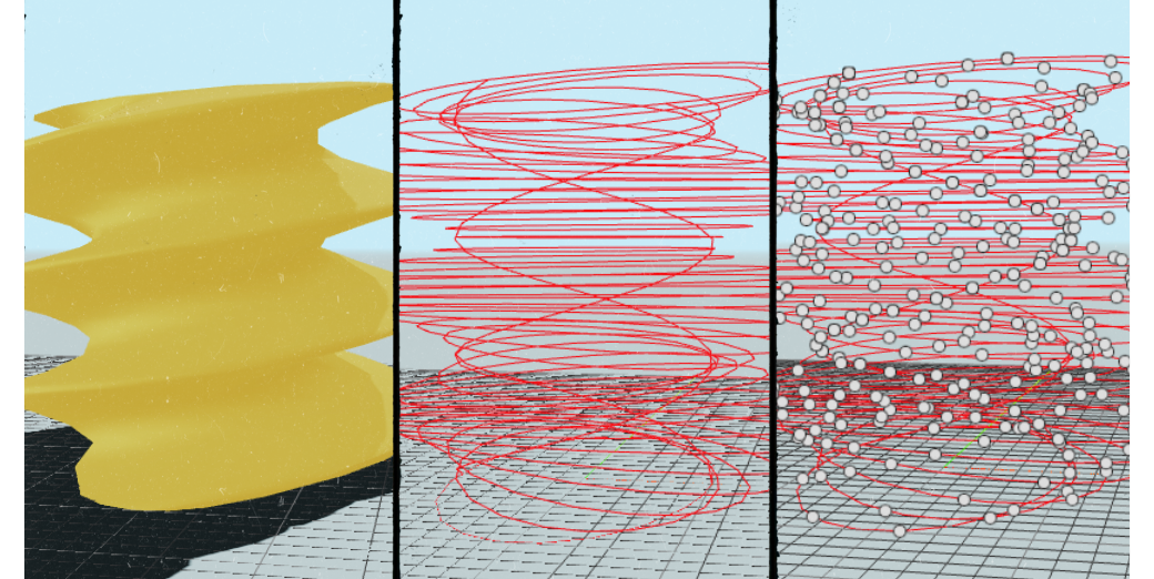
- Start with any surface that you want to slice. A lofted surface works best because it has a clean UV structure. We have taken a basic spiral vase as our model.
Required nodes:
-
- Loft Surface
- Surface Iso Curves
- Connect the Loft Surface into the Surface Iso Curves node. The output we have to use is V Iso. V Iso produces horizontal rings in UV space, which are perfect slicing profiles. Move the rings on the Z-axis by creating a List SEC as per your preferences. As you can see in the panel, the rings have now moved up from top to bottom.
2. Creating the UV sampling points

G-code slicing requires multiple rings along the height of the object. Instead of moving geometry in world space, you generate them directly in UV space that we created in the previous step. Its necessary to notice the importance the following nodes:
- List Sequence
- Construct Point
In the Construct Point, set:
-
- X = 0
- Y = 0
- Z = List Sequence from 0 to 1 with the number of layers you want
- This gives you a stack of UV coordinates that represent slicing planes along the Z axis. Connect this Construct Point node to the Point input of the Surface Iso Curves node.
BeeGraphy will now generate as many V Iso rings as you set in List Sequence.
3. Sampling points on each ring
Each ring must be divided into small segments so that a machine can follow the path.
Use:
- List Sequence
- Point On Curve
First List Sequence controls how many points will be sampled on each curve. For example, a sequence of 10 values between 0 and 1 will give you 10 points per ring.
Wire:
- V Iso → Curve input of Point On Curve
- List Sequence → Parameter input
This produces a tree of points: one list per ring.
4. Flattening all points into a single ordered path
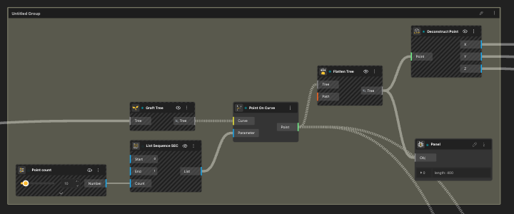
Machines follow one continuous list of G-code commands. Your points must be flattened in the order that the tool should travel.
Use:
- Flatten Tree
Wire the output from Point On Curve into Flatten Tree. You now have a single ordered list of points.
5. Calculating extrusion values (E values)
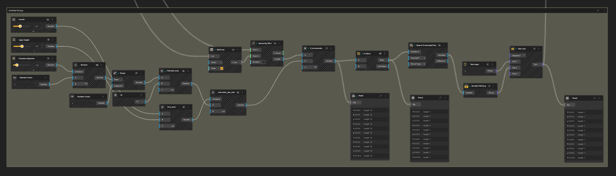
G-code for 3D printing requires extrusion calculations. Each move needs an E-value based on the distance between the current point and the next one.
Steps:
- Shift the Point List from Point on Curve by one using Shift List.
- Use Vector By 2Pnt to compute vectors between corresponding pairs.
- Use Vector Length to get segment lengths.
- Multiply each segment length by extrusion per millimeter.
- Calculating extrusion_per_mm
- Nozzle: 0.4 (Number const.)
- Layer height: 0.5 (Number const.)
- Filament Diameter: 1.74 (Number const.)
*These properties are unique to 3D-Printers. Change the values according to your printer.
-
- Divide Filament diameter by 2 to get Radius.
- Raise the power of radius to 2. Multiply the outcome with Pi. This gives us the Filament area.
- Multiply Nozzle with Layer height. This returns Line_area.
- Divide Line_area with Filament area. The resulting outcome is extrusion_per_mm.
- Multiply Vector by 2pnt length output with extrusion_per_mm.
- Pass the resulting values into Mass Addition to turn them into a cumulative sequence. These are your E values.
- Round them off to 2-3 decimal places.
- Convert this Number list to String using NumberToString.
- Use Join Text to add the letter E before the E-values.
6. Formatting G-code lines

Template:
G1 X{X} Y{Y} Z{Z} E{E} F1500
- Graft X, Y, Z from Deconstruct point and round all the values to 2-3 decimal places
- Convert NumberToString
- Use Concatenate to and X, Y and Z prefix to them respectively.
- Join the 3 lists and add the prefix G01 (used for clockwise circular movements.
- In the 4th input of text join, input out E-values from the previous text join.
- The output now looks like the template.
- This creates one G-code command per point.
7. Adding header and footer
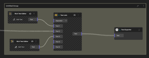
Add two Text Constant nodes for Header and Footer.
Header example:
M82
G21
G90
G28
G92 E0
G1 Z0.3 F3000
Footer example:
G1 E{E}
G1 Z10 F3000
M104 S0
M140 S0
M84
*Header and Footer are unique to printers. Please use your printer’s preferences.
Use:
- Text Join
Place the header first, then the list of G01 commands, then the footer. Set the separator to newline.
Finally, use BeeGraphy’s text exporter to save your G-code file. Your procedural geometry has now turned into machine ready instructions without using any external slicer or CAM tool.
Outcome
M82
G21
G90
G28
G92 E0
G01 Z0.3 F3000
G01 X5 Y0 Z0 E3.99
G01 X3.85 Y6.39 Z0 E3.99
G01 X0.81 Y9.87 Z0 E3.99
…
G01 X9.74 Y-1.78 Z3 E3.99
G01 X7.17 Y2.06 Z3 E3.99
G01 X1.29 Y4.83 Z3 E3.99
M104 S0
M140 S0
M84
Conclusion
BeeGraphy gives designers full control over the toolpath generation process. By combining UV based slicing, curve sampling, extrusion calculation, and text formatting inside a single node graph, you can generate custom G-code with complete creative freedom. This opens the door to advanced workflows such as procedural prints, toolpath art, machine choreography, and algorithmic fabrication.