Table of Contents
Customization creates a new design problem
A 3D printer will print any form you give it. It won’t give you the form.
For a while I’ve been thinking about starting a product design company, one that experiments with additive manufacturing and sells lamps. The more I looked at 3D printing, the clearer its two real advantages became: it makes mass customization possible, and it lets you play with form in ways a mold never would.
But the printer only solves half of that. If every customer wants a slightly different lamp, someone still has to remodel it in CAD, export it, slice it and print it, then do it all again for the next order. Customization built that way is just a lot of one-off design.
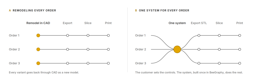
Left: how custom orders usually run. Right: the same orders through one system.
So I set myself a different question. What if the customer could change the lamp themselves, and every change was still a lamp I could print?
The controls are only the surface
The customizable 3D printed lamp itself is simple. A fluted shade made of vertical ribs sits on a base that holds a puck light. I built it as one graph in BeeGraphy, but the graph wasn’t the hard part. The hard part was deciding what someone buying a lamp should be able to change.
I ended up with eight controls on the customizable 3D printed lamp’s configurator: height, number of ribs, how far the shade bulges, the shape of the bulge, profile resolution, base height, base offset and the light holder’s diameter. The bulge shape isn’t even a number. The customer drags points on a sine curve, and the shade’s silhouette follows it.
That curve gives the customer more control than a number would. Stretch the wave and the shade gets one full, rounded bulge. Shift it and the bulges slide up or down the height. The base sliders are plainer: one sets how thick the base is, the other how far it steps out around the shade.
Profile resolution sounds like a technical setting, the kind you’d normally hide. But it changes how the lamp looks. The shade’s profile is interpolated through points sampled from that curve. More points, and the shade hugs the curve tightly. Fewer, and it relaxes into a softer version of it. So what the customer is really choosing is how literally the lamp follows the curve.
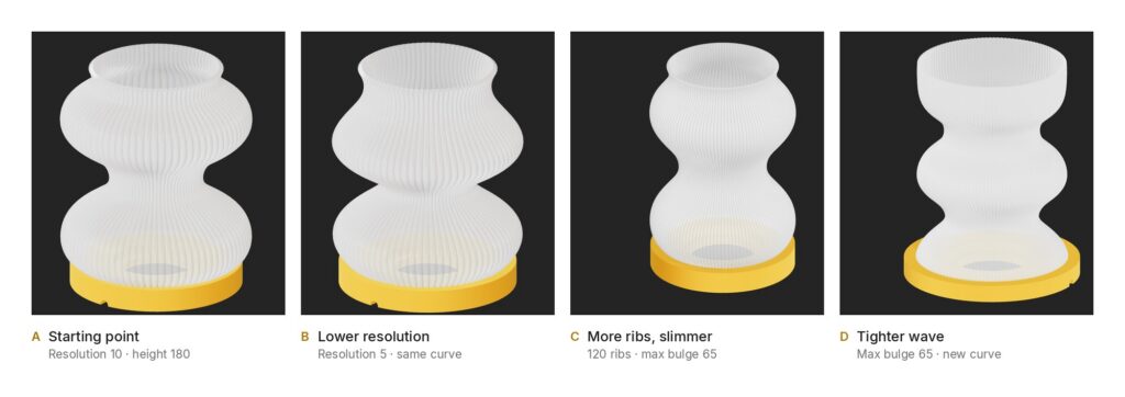
Four configurations of the customizable 3D printed lamp, taken from the configurator.
Those eight controls are what the customer sees. None of them would work on their own.
Every visible parameter needs invisible rules
Rib count shows this best. My first attempt was the obvious one. Sweep a pipe along the profile curve, then repeat it around the center. It looked bulky, and it left gaps.
The reason is that the profile’s radius keeps changing up its height. A pipe that’s the right thickness at the narrow neck is too thin at the widest point, where the ribs drift apart. Size it for the widest point and it’s too fat everywhere else. And once the rib count is a slider, any fixed thickness is wrong for nearly every setting a customer could pick.
That was the turning point. I could only give the customer the rib count if rib thickness stopped being a separate decision. It had to follow from the lamp’s shape and the number of ribs.
The rule turned out to be short. At any point on the profile, measure its distance r from the central axis. With N ribs around the circle, neighboring ribs just touch when each rib’s radius is:
rrib = r · sin(π / N)
Now the rib swells where the shade bulges and narrows at the neck, and the ribs meet whatever count the customer picks. To sweep a rib whose radius changes along its length, I used BeeGraphy’s Pipe Variable.
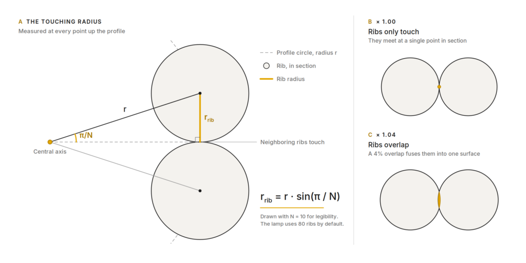
Why rib count can be a slider: each rib’s radius follows from the profile and the count.
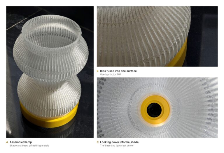
Touching wasn’t enough, though. Ribs that only touch meet along a thin line, and they don’t fuse into one solid. They needed to overlap slightly. So the rib radius gets multiplied by an overlap factor, and that factor wasn’t calculated. I kept nudging it up and checking the model. Below 1.04, thin gaps were still visible between the ribs. At 1.04, a 4% overlap, they fused. The customer never sees that number, but it’s the reason the rib-count slider can exist at all.
The bulge curve has its own hidden rule. The curve the customer draws only describes shape. The system remaps it into a real radius between a minimum and the max bulge, so dragging a point can never push the shade to a size I haven’t allowed.
The base works the same way. Its radius is never set directly. It’s measured from the bottom of the shade, and base offset only adds a margin around it, so whatever shape the customer draws, the base still fits under it. The parts of the base that hold the hardware don’t move at all: the puck light seat and the cable channel are fixed sizes, because the light and its wire don’t change when the lamp does.
Almost every value I kept hidden was protecting one I’d exposed, including the limits on the sliders themselves. One of those limits turned out to be older than the lamp it was protecting.
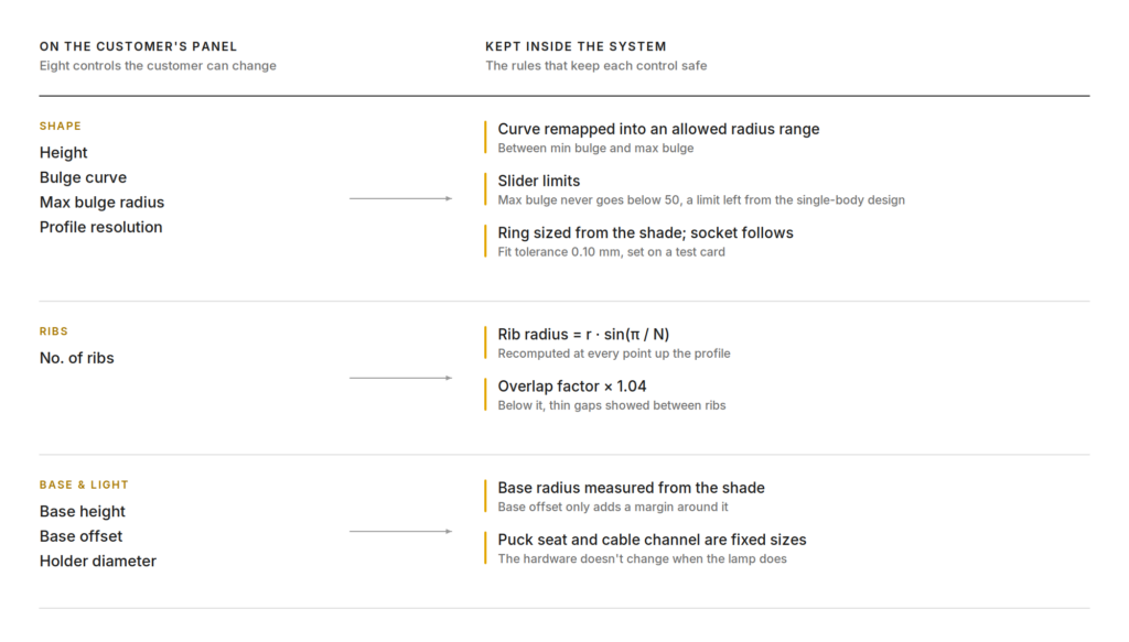
Every control on the panel is backed by rules the customer never sees.
Parametric systems preserve decisions
A parametric model keeps old decisions as rules, and they don’t announce themselves. My lamp has one.
I first imagined the customizable 3D printed lamp as a single body, with the bulb going in through the top opening of the shade. It was harder to print, harder to assemble, and the light was hard to get at. So I split it. The shade and the base became separate parts. The puck light seats in the base, and a ring at the bottom of the shade drops into a socket cut into the base. The ring’s size is taken from the shade itself, so it changes with every configuration, and the socket follows it.
The split left something behind. Max bulge can’t go below 50, a floor I set when the bulb still had to go in from the top. Once the light moved into the base, that reason was gone, but I never went back and updated the limit. It still stops the lamp getting slimmer, for a reason that no longer exists.
That’s the risk of building a system rather than an object. A one-off model gets thrown away along with its mistakes. A system carries them into every lamp it makes.
The physical world becomes another parameter
Not every rule in the system came from the screen. The ring and socket only work with a small gap between them, and that gap can’t be decided digitally.
I worked it out away from the lamp, on a printed tolerance test card with gaps in 0.05 mm steps. The fit I was after sat between 0.10 and 0.15 mm. On my Bambu Lab A1 with PLA, 0.10 mm worked better, so that’s the number in the system.
It’s another hidden value, and the customer doesn’t need to know it exists. But it’s the one number in the lamp that came from the printer, and I wouldn’t assume it carries over to another printer or material.
It does stay adjustable inside the graph, on its own slider running from 0.1 to 0.45, just never on the customer’s panel. If the printer or the material changes, that’s the number to retest.
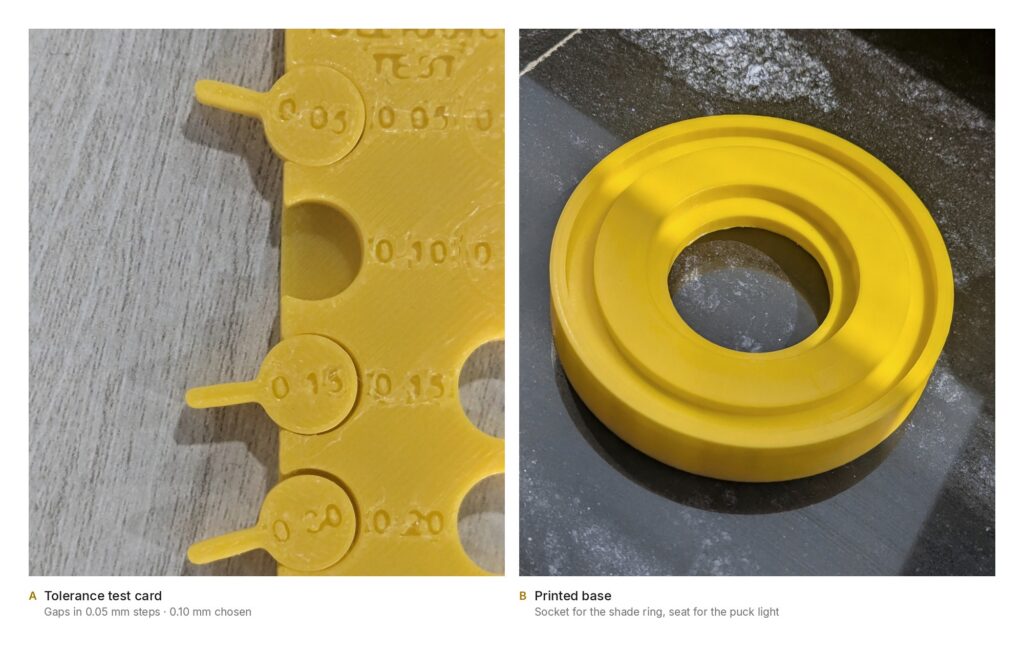
The fit was settled on a test card before it went into the system.
The system itself needs to be designed
The last thing I had to design wasn’t part of the lamp. At first everything lived in one output. Then the configurator preview got slow. The heavy operations, fusing the shade into one solid and adding the fitting details, were dragging it down.
So I split the system into two outputs from the same definition. The customer gets a lightweight preview that responds quickly. The manufacturing output carries the heavy operations and exports STL files for printing. In the live graph, those manufacturing steps are switched off on purpose: their job is done once a design is exported.
The preview is the same definition with the steps only the printer needs left out. It’s what the customer configures and downloads, and BeeGraphy lets a manufacturer embed it on their own website. To show that route, we set it up on a demo manufacturer site.
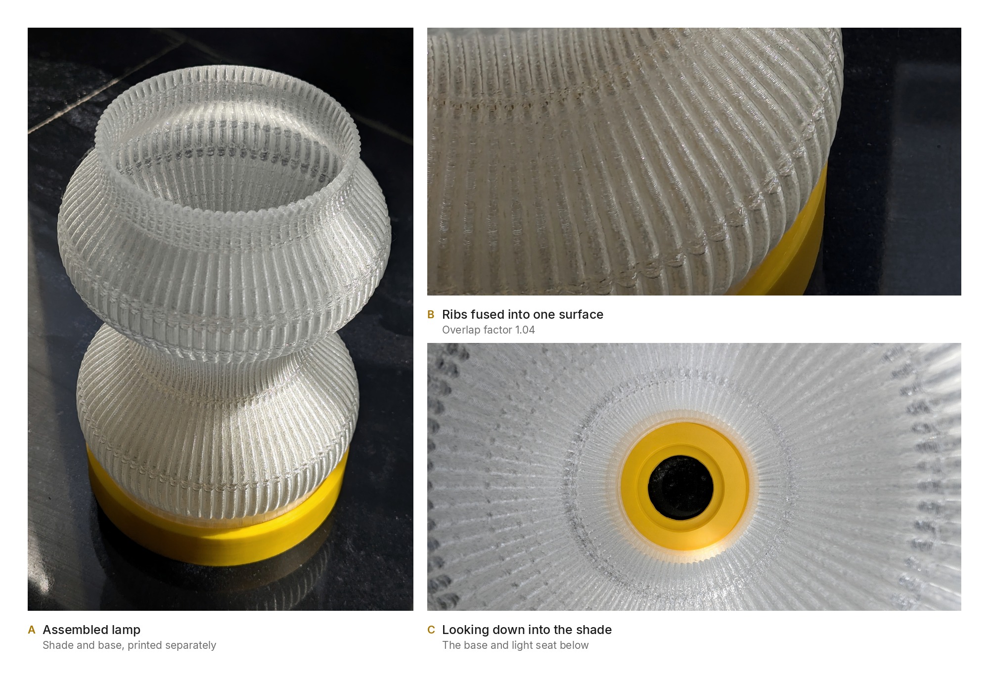
That’s the route the customizable 3D printed lamp in these photos took. I exported the shade and base as separate STLs, sliced them in Bambu Studio and printed them in PLA on the A1. The print came out successfully.
Design work doesn’t disappear. It moves.
Holder diameter is on the customer’s panel because I wanted to leave room for someone who’d rather use a bulb holder than a puck light. But that isn’t a range. It’s a choice between two fittings. A slider suggests any diameter means something, when what I had in mind was two options. Offering exactly those two would have said what the control really is. I missed it.
That miss sums up the customizable 3D printed lamp project for me. I wasn’t reshaping lamps anymore. I was deciding, ahead of time, what a customer could change, what form each change should take, and what must never move.
Looking back, most of those decisions are ones the customer will never see: a formula for rib thickness, a 4% overlap, a 0.10 mm gap, a limit I forgot to retire, an output switched off on purpose.
That takes systematic thinking, and it’s as much design as the ribs are. The eight controls are the part anyone can see. The decisions behind them are the part worth designing.
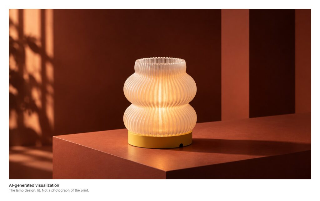
AI-generated visualization of the customizable 3D printed lamp. Not a photograph of the print.
Try the customizable 3D printed lamp yourself
The customizable 3D printed lamp configurator below runs on the same system this article describes. Change the controls and watch the ribs and the base follow.
Customizable 3D printed lamp FAQ
What can a customer change on the customizable 3D printed lamp?
The customizable 3D printed lamp has eight controls: height, number of ribs, how far the shade bulges, the shape of the bulge, profile resolution, base height, base offset and the light holder’s diameter. The bulge shape isn’t a number. The customer drags points on a sine curve and the silhouette follows it.
How do the ribs of the customizable 3D printed lamp stay fused at any rib count?
Each rib’s radius isn’t set by hand. It follows r · sin(π / N), where r is the profile’s distance from the axis and N is the rib count, so neighboring ribs always meet. A 4% overlap on top of that makes them fuse into one solid.
What printer and material was the customizable 3D printed lamp printed on?
PLA on a Bambu Lab A1. The shade and base were exported as separate STLs and sliced in Bambu Studio. The ring and socket use a 0.10 mm gap found on a tolerance test card, which is the number to retest on a different printer or material.
Can a manufacturer put this configurator on their own website?
Yes. BeeGraphy lets a manufacturer embed the lightweight preview of the customizable 3D printed lamp on their own site, while the manufacturing output from the same definition produces the STL files for printing.