Table of Contents
Every product cut from a sheet of material begins as a flat shape. Before any laser, router, or saw starts work, those shapes have to be arranged on the raw material so they use the space as well as possible. That arrangement is called nesting: the art and science of fitting as many parts as you can onto a sheet while wasting as little material as possible.
The idea is old. Tailors have done a version of it for centuries, shuffling pattern pieces across a bolt of fabric to leave the smallest possible scraps. The same puzzle shows up today wherever things are cut from sheet stock: 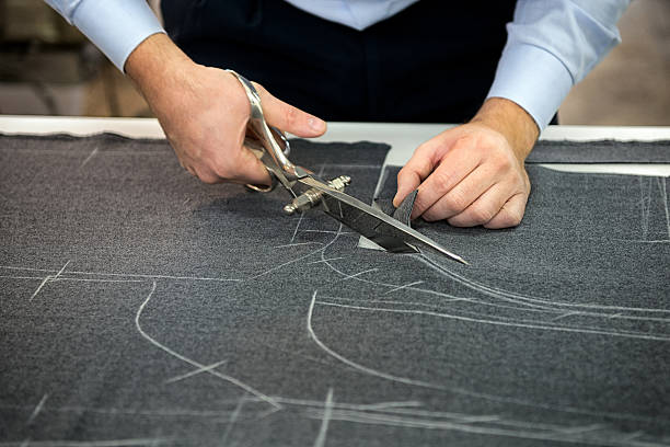
- Sheet metal and laser cutting, where a few percent of yield decides whether a job turns a profit.
- Woodworking and CNC routing, packing cabinet and furniture panels onto plywood.
- Textiles, leather, and apparel, fitting irregular pieces onto material that is rarely cheap.
- Packaging, where folded and die-cut shapes have to share a sheet.
- Glass, composites, and stone, where every offcut is expensive.
It looks like a small preparatory step. In reality it is one of the most consequential decisions in manufacturing, because every square centimeter saved is money saved. Good nesting is the difference between a run that makes money and one that quietly bleeds it.
Why nesting belongs in the design process
Modern manufacturing leans on parametric design because it makes customization scalable. Instead of drawing each variation by hand, a single parametric model can produce hundreds of unique configurations just by adjusting its inputs. Change a dimension, a material, or a part count, and a new production-ready design appears almost instantly.
Traditional nesting works against that flexibility. Because design and nesting usually live in separate tools, parts have to be exported before they can be laid out for manufacturing. So every time the design changes, the nesting has to be redone. Even a small update turns into a repetitive loop of file transfers and re-arranging, slowing down the very workflow parametric design was meant to speed up.
This is most obvious the moment you scale customization. Product configurators push parametric design all the way to the customer: someone personalizes a product online, and a production-ready design comes out the other end. But a custom order is only truly production-ready once its parts are nested, and no two custom orders have the same parts. You cannot pre-arrange a layout you have never seen.
BeeGraphy solves this by building nesting directly into the design environment, so the production layout stays tied to the logic that generates the geometry. When dimensions change, quantities update, or sheet sizes are modified, the nest adapts automatically as part of the same workflow. A customer configures a one-off shelving unit, and its unique set of parts nests itself, with nobody laying out shapes by hand. The design and its production layout stay in sync from start to finish. That is something a design-then-export-to-separate-software pipeline simply cannot do at scale.
A look at the in-house nesting nodes
BeeGraphy ships a built-in Nesting plugin that has grown quickly. Its nodes are split into two groups: Rectangular Nesting for box-based layouts, and True Shape Nesting for packing real contours. Together they span the full range, from an instant rough preview to a tightly optimized production run.
Rectangular Nesting
This group packs parts using their bounding boxes, the simple rectangles that surround each shape. Treating parts as rectangles rather than their real geometry keeps nesting fast and easy to compute, which works well for rectangular or regular parts and wastes space on complex ones. Which node you pick comes down to two things: how much computing time you want to spend, and what your cutting machine can physically do.
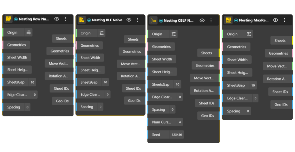
- Row Naive places parts one after another in straight horizontal rows, starting a new row below once the current one fills. Its plain straight-row output is quick to generate, which makes it useful for live previews while you design, and it suits straight-cut machines such as panel saws and table saws.
- BLF Naive (Bottom-Left-Fill) drops each part into the lowest spot it can reach, then slides it as far left as it will go, with no backtracking. This produces a freely packed layout where parts are not in clean rows, so it is meant for machines that can follow any path: laser cutters, CNC routers, waterjet, and plasma.
- CBLF Naive (Corner-Bottom-Left-Fill) works the same way but settles each part into the lowest available corner, and it can try several different orderings and keep the best. Like BLF, it produces a free-placed layout for any-path machines: laser, router, waterjet, and plasma.
- MaxRects Best Fit tracks all the open rectangles left on the sheet and places each part in the one where it leaves the least wasted space. It is also free placement, so it runs on any-path machines: laser cutters, CNC routers, waterjet, and plasma.
Nesting Nodes for Rectangle Packing
- Guillotine Best Fit places parts under one rule: every cut must run straight across the sheet from edge to edge. That makes its layout directly cuttable on straight-cut machines, such as panel saws, beam saws, and glass cutting tables.
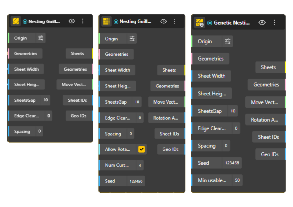
- Genetic Guillotine Best Fit produces the same straight, edge-to-edge guillotine layout, but uses a genetic algorithm that evolves many arrangements and keeps the best. It needs more computing time than the plain version and is built for the same machines: panel saws, beam saws, and format cutters.
- Guillotine 3-Stage cuts the sheet into horizontal strips, then vertical stacks, then individual parts. This staged pattern maps onto how industrial format-cutting machines work, such as CNC beam saws, so it is the choice when your line uses that equipment.
Nesting Nodes for Guillotine
True Shape Nesting
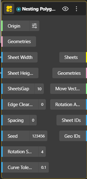
This group is for irregular parts, where packing the bounding box would waste too much material. Its Polygon Genetic node works directly with the real outline of each part. It uses a genetic algorithm together with bitmap collision detection, which rasterizes each shape into pixels to test overlap quickly, so it can handle complex and concave contours. It also supports multi-angle rotation, so parts turn to find their best fit, and hole filling, so smaller parts nest inside the openings of larger ones. Because it follows any path, it is for laser cutters, waterjet, plasma, CNC routers, and knife or drag cutters used on fabric, leather, vinyl, and cardboard.
The plugin is still under active development, so expect this lineup to keep growing.
What each node’s output looks like
The best way to feel the difference between the packers is to run the same parts through each and watch the layout change. Here is the same set of shapes nested by every node.
Row Naive. Parts line up in clean horizontal rows, a new row starting once the last is full. The most orderly, grid-like result. 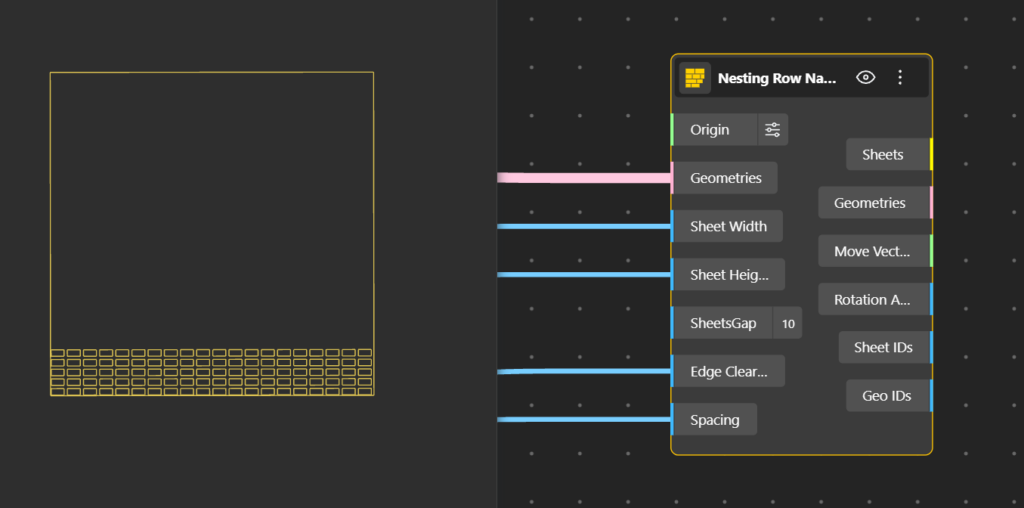
BLF Naive. Parts settle down and to the left, dropping into the gaps left by earlier pieces, so the layout looks packed rather than ruled into rows.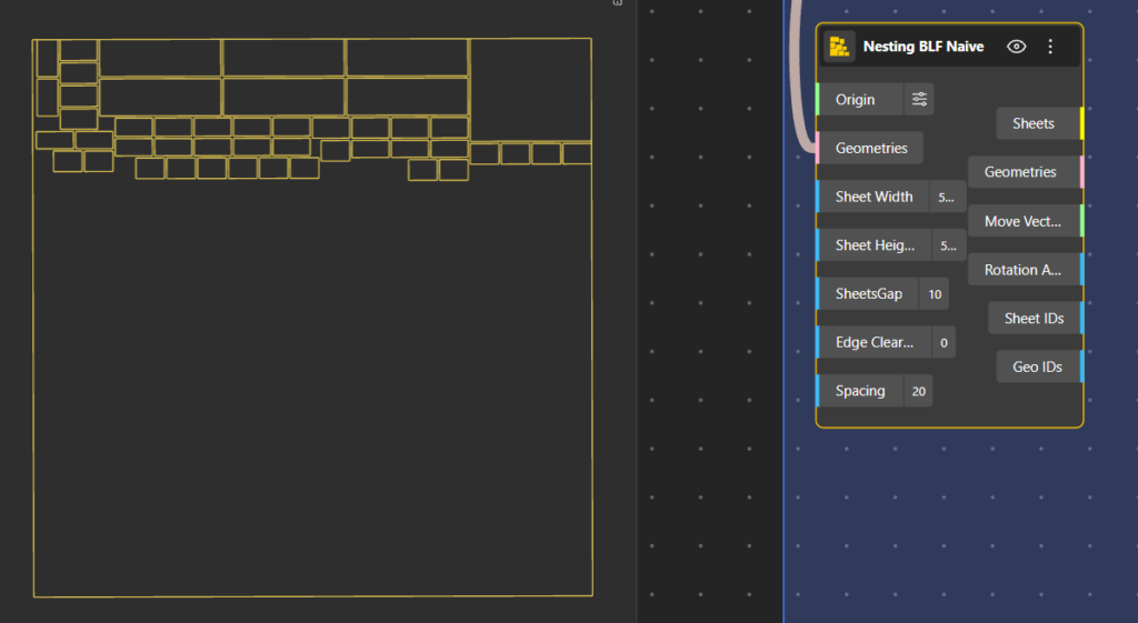
CBLF Naive. Similar to BLF, but parts tuck into the lowest available corners, giving a slightly more interlocked look.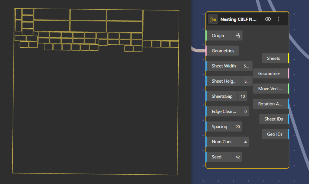
MaxRects Best Fit. Parts drop into the best-fitting open rectangle on the sheet, so they fill the space more evenly with fewer obvious gaps.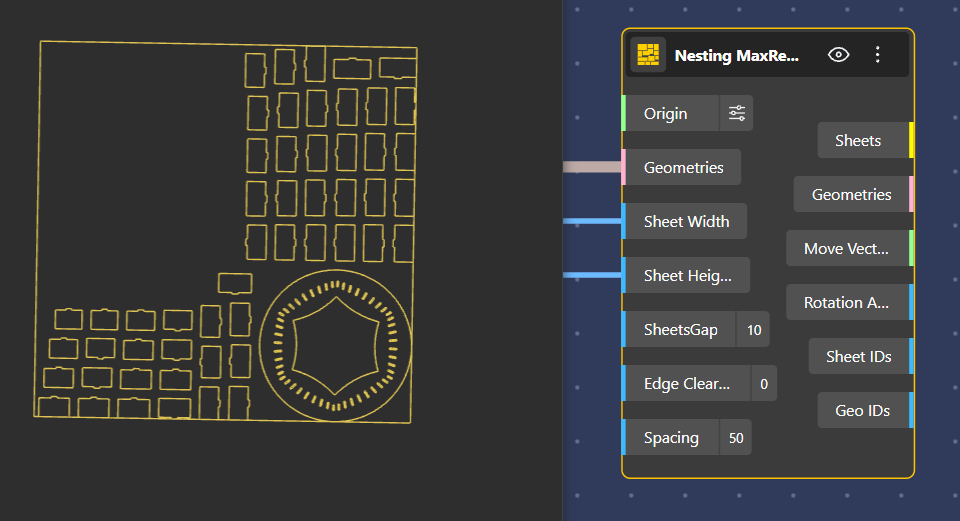
Guillotine Best Fit. Parts are arranged so the whole sheet can be cleared with straight cuts running edge to edge, giving a distinctly banded, saw-ready layout.
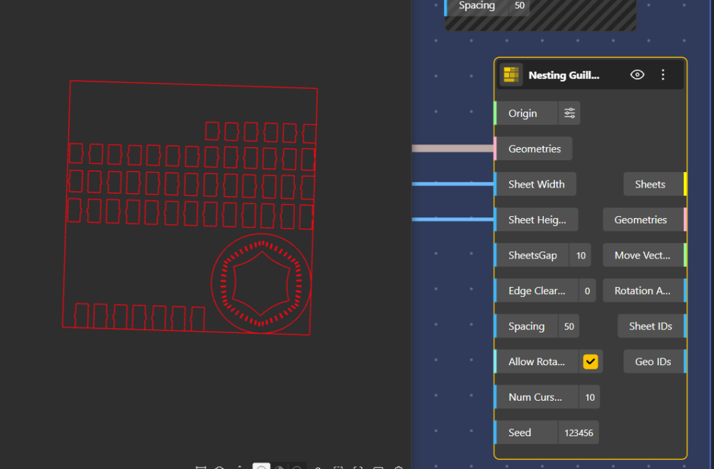
Genetic Nesting Guillotine Best Fit. The same straight-cut, edge-to-edge structure, but the arrangement is refined by the genetic search for a closer pack.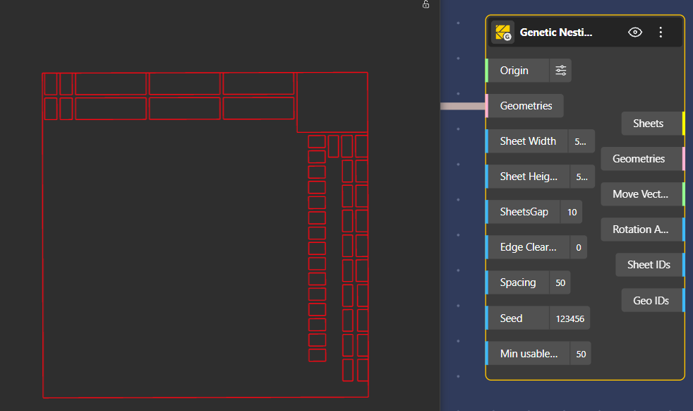
Guillotine 3-Stage. A clearly staged look: the sheet reads as horizontal strips, those strips as vertical stacks, and the stacks as parts.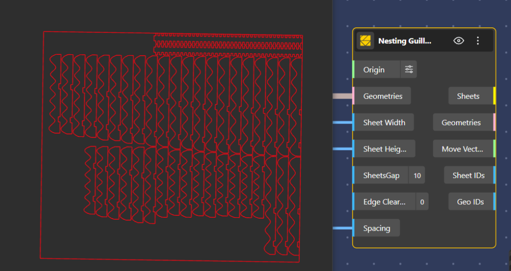
Nesting Polygon Genetic. Real outlines interlock, parts rotate to fit, and small pieces sit inside the holes of larger ones, the tightest and most organic-looking result.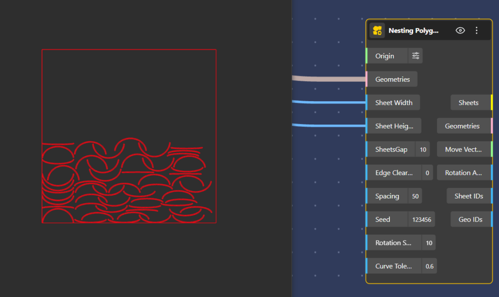
Node Inports
- Origin (Vector, default [0,0,0]): Where the nested sheet layout gets placed in space. Origin point for sheet placement.
- Geometries (Geometry): The parts to nest. On the true-shape node this can be curves or surfaces; on the rectangular nodes it is the list of shapes to pack.
- Sheet Width / Sheet Height (Number, default 500 each): Your raw stock size. This is the material you are cutting from.
- SheetsGap (Number, default 10): Worth being clear on this one: it is only the spacing between sheets when they are laid out in the output. It is a display/layout gap between multiple result sheets, not anything physical on the material.
- Edge Clearance (Number, default 0):. The margin to keep clear around the sheet edge. The 3-stage node spells out what this is for in practice: a trim allowance, the margin from the sheet edges.
- Spacing (Number, default 0): The gap held between parts. This is the practical one: the 3-stage doc names it directly as the gap between parts, the kerf or blade thickness. This is how you account for the width the cutter physically removes
Additional Inports
The simplest packers run once and give a predictable result. The more capable nodes add a few controls that let you trade a little time for a tighter layout:
- Num Cursors: Tells the node how many different arrangements to try before keeping the best one. Higher means it works harder and packs tighter; lower means a faster answer. It is your speed-versus-density trade as a single number.
Found on CBLF Naive and Guillotine 3-Stage. - Seed:Locks in a node’s randomness so it produces the exact same layout every time, rather than a slightly different one on each run. Change the number for a fresh attempt.
Found on CBLF Naive, Genetic Guillotine, Guillotine 3-Stage, and Polygon Genetic. - Allow Rotation: A simple on/off switch for flipping parts 90 degrees to fit them in better.
Found on Guillotine 3-Stage. - Rotation Steps: The finer version of rotation: a value of 4 tries parts at 0, 90, 180, and 270 degrees, and higher values test more angles in between to fit awkward shapes.
Found on Polygon Genetic. - Min usable size: Sets how small a leftover piece can be and still count as a reusable offcut instead of scrap, so good remnants don’t get thrown away. Found on Genetic Guillotine.
- Curve Tolerance: Sets how closely the true-shape packer follows a curved outline. Tighten it for accuracy on rounded parts, loosen it for speed.
Found on Polygon Genetic.
Node Outports
- Sheets (Curve): The boundary rectangle for each sheet used. Count these and you know how many sheets the job consumes.
- Geometries (Geometry): The parts moved into their final nested positions.
- Move Vectors (Vector) and Rotation Angles (Number, radians): The transform applied to each part: how far it moved and how far it turned. These align with your input order, so you can apply them back onto your original model instead of using the placed output, which is how you keep material, IDs, and colors attached to each part.
- Sheet IDs (Number): Which sheet each part landed on. Critically, parts that did not fit get a value of -1. That -1 is your overflow flag: it tells you exactly which parts ran off the available sheets so you can add stock or resize.
- Geo IDs (Number): The original input index for each nested part, so every cut piece traces back to its place in the model
From CAD to CAM
Nesting is where a design platform turns into a manufacturing platform. It is the bridge between CAD, the world of geometry and intent, and CAM, the world of machines and material. In BeeGraphy that bridge is not a file export into separate software. It is a continuous chain of nodes that carries your design straight through to the cut.
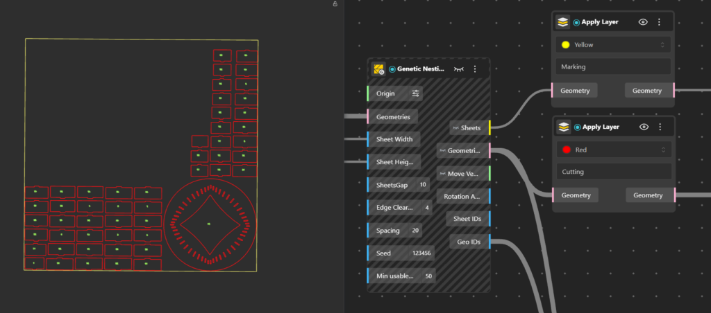
Giving the layout meaning: the Apply Layer node
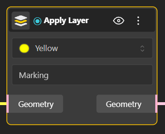
A freshly nested layout is still just shapes on a rectangle. It does not yet know what it is made of, or what the machine should do with each line. The Apply Layer node fills both gaps.
First, it assigns a real material to your parts, so the layout carries actual numbers like thickness and sheet size instead of dimensionless outlines. The nest you see now reflects the material you will really cut.
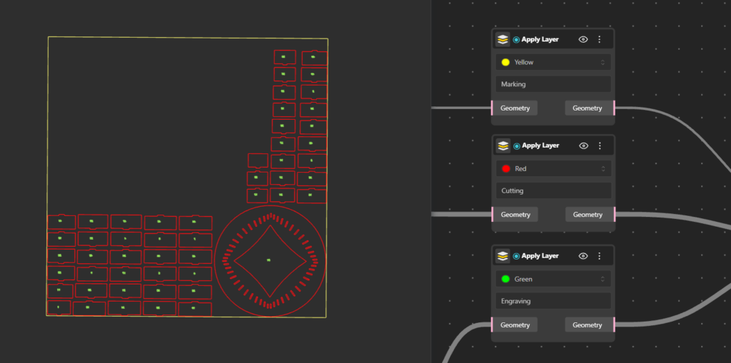
Second, it color-codes every line by the operation the machine should perform, the same convention most laser and CNC setups already use to tell one job from another:
- Red for cutting
- Yellow for marking
- Blue for internal cutting
- Green for engraving
- Magenta for hatching and filled areas
- Cyan for dimensions and annotations
So a single part can carry its outline to be cut, its detail to be engraved, and its text to be marked, all in one file, each in its own color, ready to run with no manual sorting.
Knowing what goes where: Sheet ID and Geo ID
The moment a design leaves the screen, it becomes a pile of look-alike pieces. Which sheet does each part come from? Where does each cut piece belong once it is made? BeeGraphy’s nesting nodes answer both by giving every part two labels.
- The Sheet ID says which physical sheet a part is cut from. A nest rarely fits on a single sheet, so this tells you that part belongs on sheet one, this one on sheet two, and so on. Walk to the machine with three boards and you know exactly what comes off each.
- The Geo ID is a unique tag tied to each individual geometry, tracing every cut piece back to its exact place in the original parametric model.
Together they give you traceability, something disconnected pipelines lose entirely. Before cutting, you can cross-check that the right part came from the right place in the design. After cutting, assembly stops being guesswork: instead of puzzling over identical-looking pieces, you match IDs and every part snaps to where it belongs.
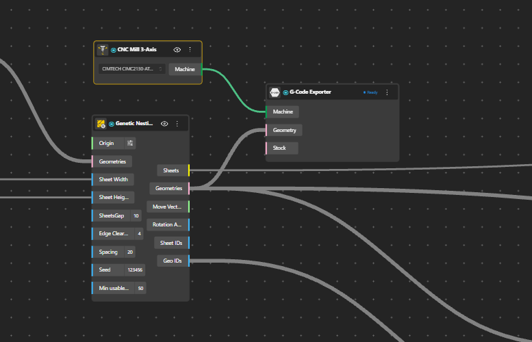
Driving the machine
With material and operations assigned, the layout is ready to cut. You wire it into the Machine node to connect directly to your fabrication setup, and into the G-code node to generate the instructions that actually drive the cut. The geometry you designed becomes a toolpath without ever leaving the environment or losing its parametric link to the model upstream.
That is the real payoff of keeping CAD and CAM in one place. The design produces the parts, the nest arranges them, Apply Material gives them meaning, the IDs keep them traceable, and the CAM nodes cut them. Change something upstream and the whole chain updates, IDs and all. You build the logic once, and it follows you to the machine and back.
One workflow, from design to cut
Nesting may happen near the end of the design process, but its impact reaches far beyond material layout. It shapes how much stock you use, what production costs, how efficiently you manufacture, and how smoothly a design moves from concept to reality. When nesting is disconnected from design, every change creates extra work. When it is built into a parametric system, the design and its production layout evolve together. By bringing nesting directly into BeeGraphy, you keep geometry, material optimization, and manufacturing preparation connected in a single continuous workflow.
Ready to take your designs from parametric model to production-ready layout in one continuous process? Explore Nesting in BeeGraphy and see how it fits into your workflow.