Table of Contents
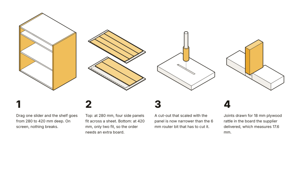
Drag one slider and a shelf gets deeper. On screen, nothing breaks. The panels grow, the slots follow, and the preview updates before you let go of the mouse.
In the workshop, three things break. The side panels, which fitted four across a 2440 × 1220 mm sheet at 280 mm deep, now fit only two at 420 mm, so the order needs an extra board. A decorative cut-out that scaled with the panel is now narrower than the 6 mm router bit that has to cut it. And the joints, drawn for 18 mm plywood, rattle in the sheets the supplier actually delivered, which measure closer to 17.6 mm.
The model drew a shelf the machine could not make, and nobody found out until it was cut. Closing that gap between what a model can draw and what a workshop can build is what parametric design for manufacturing is for.
Why most parametric models are built for the screen
Geometry has no limits. A curve can be any length, a corner can be perfectly sharp, and a wall can be a tenth of a millimetre thick. Software will draw all of it without complaint. Machines and materials are not so forgiving: a router bit is round, a sheet of board has an edge, and a printer cannot hold a steep overhang in mid-air.
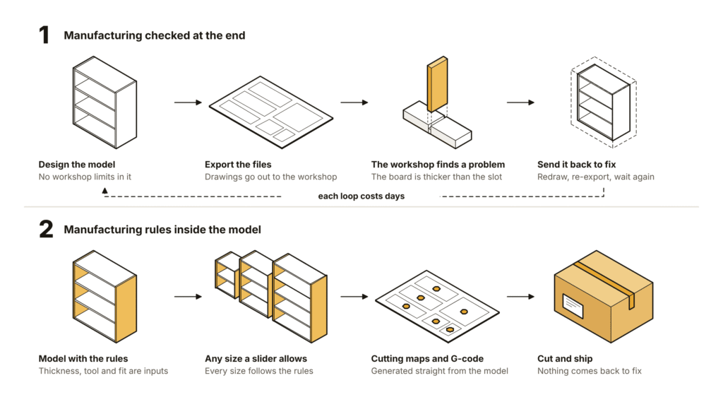
In most workflows, manufacturing is a check that happens at the end. The designer finishes the parametric model and exports it. The workshop opens the file, finds the problem and sends it back. By then the designer is working on something else, and each round trip costs days.
For a one-off object, that loop is annoying but survivable: you fix the file once and move on. A parametric model is different, because it is not one object. It is a system that produces objects, and it carries every rule you give it into every variant it makes. One wrong rule in a parametric model with five sliders is not one bad part. It is every bad combination those sliders allow.
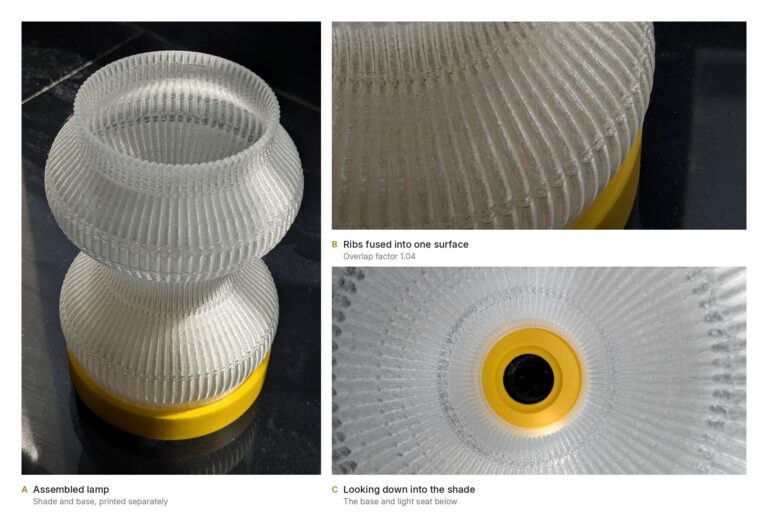
I ran into a version of this on my configurable 3D-printed lamp. A limit I set early in the project kept constraining every lamp long after the reason for it had gone. A one-off model would have thrown that mistake away. The system kept it.
Parametric design for manufacturing turns the usual order around. Instead of checking the output against the workshop’s limits, you put those limits inside the parametric model, so the loop never starts. The broader idea, design for manufacturability, is decades old. What changes with parametric models is that the rules have to hold for every variant, not just the one on screen.
What it means for a model to understand manufacturing
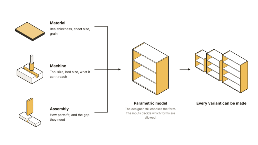
A parametric model that understands manufacturing knows three things about the world outside the screen:
- The material: how thick it really is, how big the sheets come, and which way the grain runs.
- The machine: the size of the tool, the size of the bed, and the shapes it cannot reach.
- The assembly: how parts fit together, and how much gap they need to do it.
These are inputs to the parametric model, not checks on its output. They sit alongside the sliders a designer or customer moves, and they decide which values those sliders are allowed to take.
None of this takes the design away from the designer. You still decide the form. The rules decide which forms can leave the building. A model does not need to know everything about a factory, either. It needs a handful of numbers that, if they were wrong, would make a part impossible to make.
5 rules of parametric design for manufacturing
These five rules cover most of what goes wrong between a parametric model and a CNC router, a laser cutter or a 3D printer. Each one is small. Together they decide whether a slider produces a product or a problem.
1. Material thickness is a variable, not a number
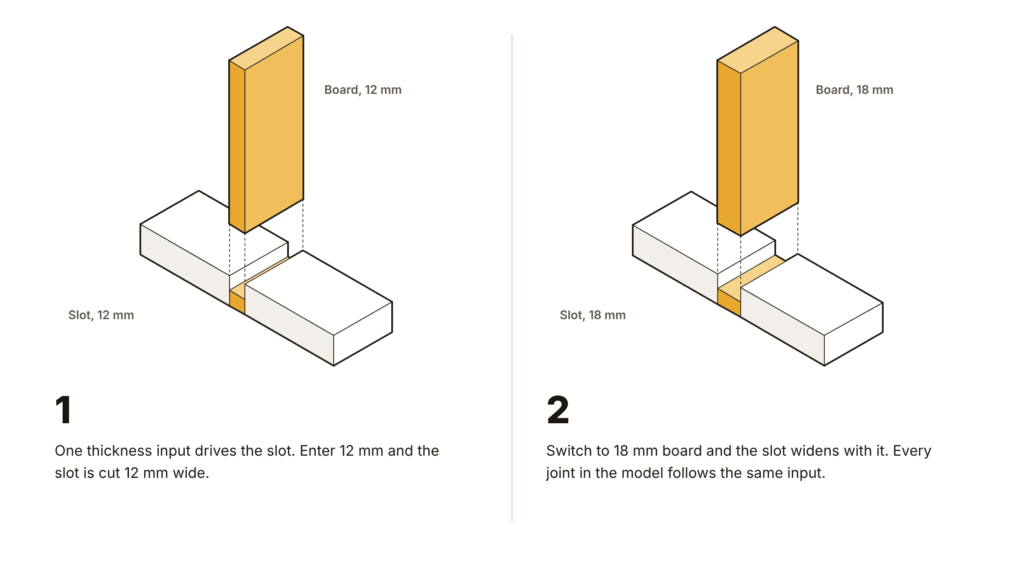
Plywood sold as 18 mm is rarely exactly 18 mm. It varies from supplier to supplier and sometimes from batch to batch. And the same product may need to switch from 12 mm to 18 mm board when a customer wants something sturdier or a supplier runs out.
If slot widths are typed in as fixed numbers, every one of those changes breaks the joints. Slots that are too wide rattle; slots that are too narrow will not close at all.
The rule: one thickness input drives every slot, tab and offset in the parametric model. Measure the real board, enter it once, and every joint follows.
2. The tool has a radius
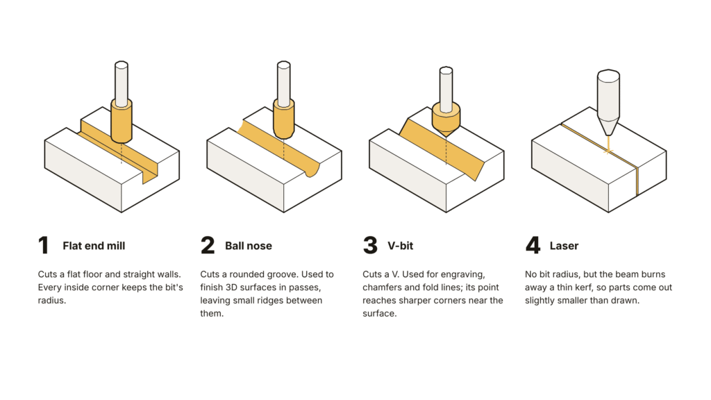
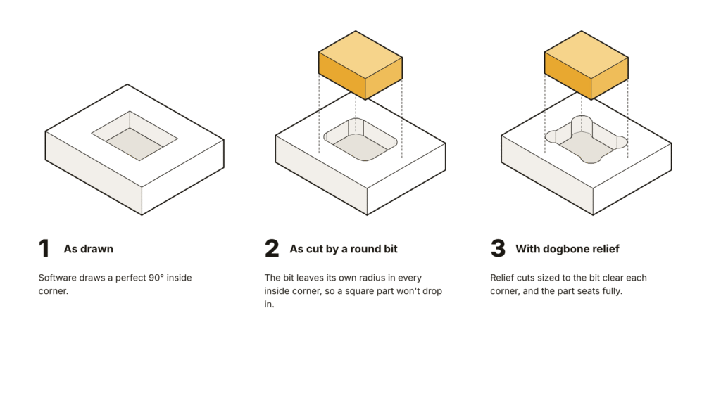
A router bit is round, so it cannot cut a sharp inside corner. Wherever the drawing has a perfect 90-degree corner on the inside of a cut, the machine leaves a small curve with the radius of the bit. On a slot-together joint, that curve is enough to stop the mating part from seating.
The rule: every inside corner either gets a relief cut sized to the bit, usually called a dogbone, or is designed to avoid a sharp corner in the first place. In BeeGraphy, the November 2026 update added a dogbone toolpath that adds these relief cuts automatically and lets you preview where they go.
3. The machine and the sheet have a size
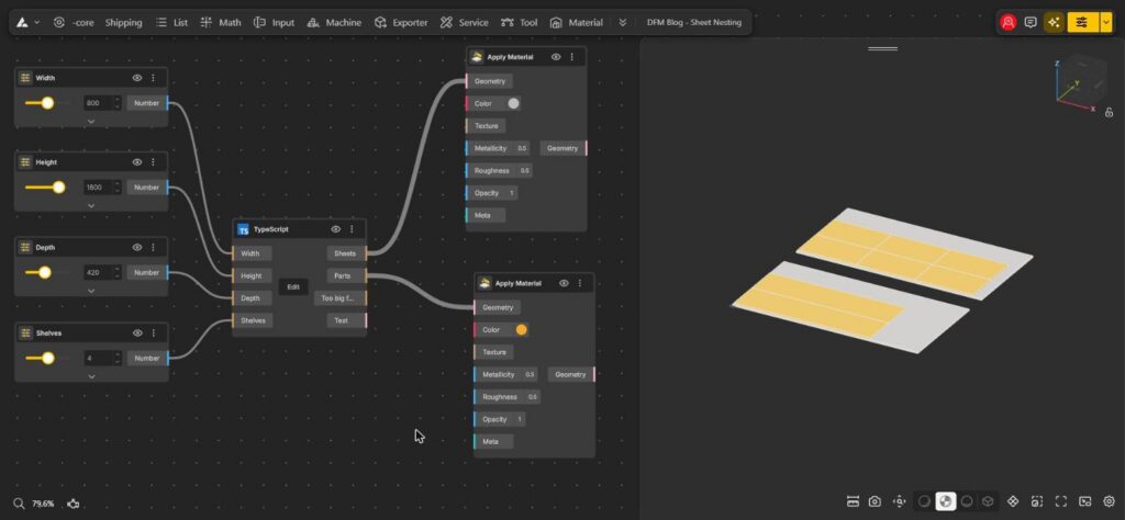
A part longer than the sheet, or larger than the machine bed, cannot be cut in one piece. At the other end, a part that is too small may not stay put on a router while it is being cut. BeeGraphy, for example, routes parts under 30 × 30 mm to the format saw by default rather than the router.
Size also decides cost. As the shelf in the introduction showed, a few centimetres of depth can turn four parts per sheet into two.
The rule: the limits on every slider come from the sheet and bed size, so no customer can drag a part past them, and part sizes are known before nesting lays them out on the board.
4. Parts need a gap to fit
Two parts drawn to exactly the same size will not slide together. A peg drawn at 10 mm will not go into a hole drawn at 10 mm. They need a small clearance, and the right amount depends on the machine, the material and even the settings.
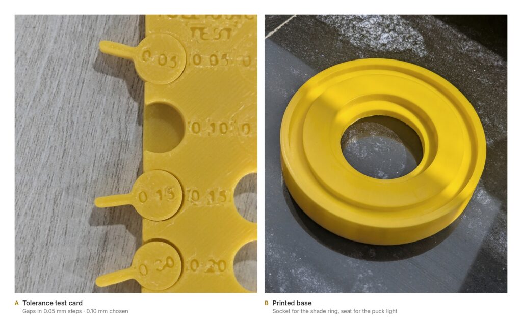
That makes clearance a number you find by testing, not by guessing. For my lamp, the ring at the bottom of the shade drops into a socket in the base. I printed a test card with gaps in 0.05 mm steps and found that 0.10 mm worked best on a Bambu Lab A1 with PLA. That number would need retesting on a different printer or filament.
The rule: clearance is a hidden parameter, set per machine and material, and every fitted joint in the model uses it.
5. Direction matters
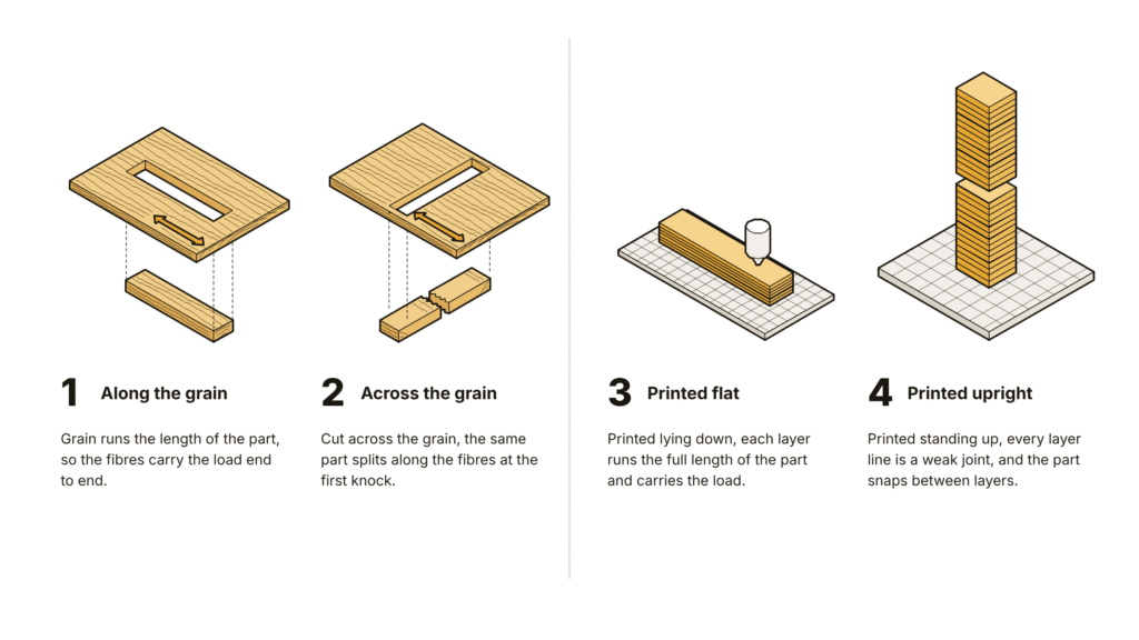
Materials are not the same in every direction. Wood is stronger along the grain than across it, and a long thin part cut across the grain can snap. A visible panel cut in the wrong direction also looks wrong next to its neighbours.
3D printing has the same issue in a different form. A printed part is weakest between its layers, and overhangs steeper than about 45 degrees usually need support material that leaves marks.
The rule: the parametric model records which way each part should be cut or printed. Nesting then respects the grain instead of rotating parts freely to save space, and print orientation is decided by the design rather than left to the slicer.
Where the rules live: hidden parameters and safe ranges
Most of these rules should never appear on a customer’s screen. Nobody buying a shelf wants a slider for router bit radius, and nobody buying a lamp wants to set a print clearance.
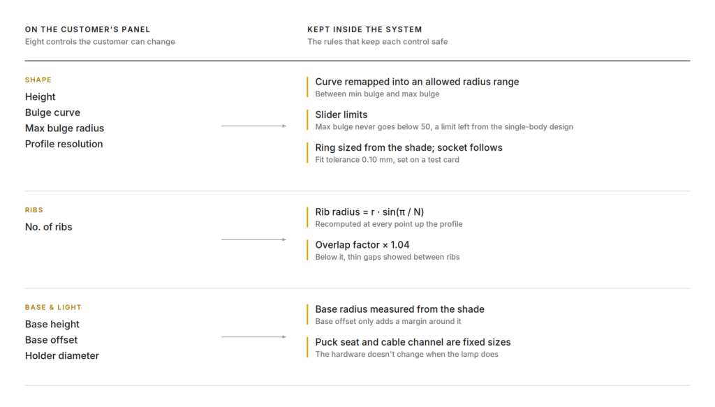
My lamp’s configurator shows eight controls: height, number of ribs, bulge, the shape of the bulge, profile resolution, base height, base offset and holder diameter. Behind them sit the rules that keep every combination printable: a formula that sizes each rib from the profile and the rib count, a 4% overlap so the ribs fuse into one solid, and the 0.10 mm gap at the socket. The customer never sees any of them, and every lamp they configure can still be printed.
The visible sliders need protecting too. Each one gets a minimum and maximum that only allows values the workshop can make. A slider that goes from 0 to 1000 is an invitation to order something impossible.
One warning from experience: hidden rules are easy to forget. A limit set for a reason that no longer applies will keep shaping every product until someone reviews it. When the product changes, check the hidden rules as well as the visible ones.
What changes when your model understands manufacturing
When the rules are inside the model, the work around it changes in three ways.
Every variant can be made. A designer can hand the model to a customer, or to a colleague, without checking each result by hand. The review that used to happen on every order happens once, when the rules are set.
Quotes become accurate. Material use, sheet count and cut length come from the real parts at their real sizes, so the price reflects what the order will actually cost to make. There is no gap between the shelf that was quoted and the shelf that gets cut.
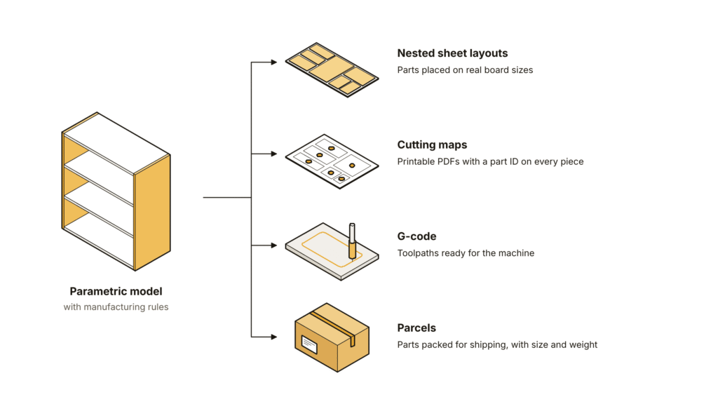
The same model goes straight to production. In BeeGraphy, the model that drives the configurator also produces nested sheet layouts, printable cutting maps, G-code for the machine and the parcels an order ships in. The manufacturing platform overview and our furniture manufacturing workflow post show how those pieces connect.
That is the real payoff of parametric design for manufacturing. The designer stops being the bottleneck between a customer’s choice and a finished product.
Before you publish a model: 8 questions
Run through these before you share a model with customers or send it to a workshop. A “no” to any of them is a variant waiting to fail.
Parametric design for manufacturing: FAQ
What is parametric design for manufacturing?
It is the practice of building material, machine and assembly rules into a parametric model, so every variant the model produces can actually be made. Thickness, tool size, sheet size, clearance and direction become inputs to the model rather than checks done after export.
How is it different from design for manufacturing (DFM)?
DFM is the general practice of designing products so they are easy and cheap to produce. Parametric design for manufacturing applies the same thinking to models that generate many variants, where each rule has to hold across every combination of sliders, not just one finished design.
Which rules matter most for CNC furniture?
Start with material thickness, the tool radius at inside corners, the sheet size and the clearance on every joint. Those four cause most of the failures between a furniture model and a finished piece.
Does building in manufacturing rules limit creativity?
It limits the forms a machine cannot make, which were never going to leave the workshop anyway. Inside those limits the designer still chooses the form, and some limits end up shaping the design’s best features.
Can I add manufacturing rules to a model I have already built?
Yes, but expect to rewire it. Start with material thickness: find every number that assumes a board size and replace it with one thickness input. Then add the tool radius to inside corners, a clearance value to every fitted joint, and limits on the sliders so no variant outgrows the sheet. Retrofitting a parametric model takes longer than building the rules in from the start, so new models are the best place to begin.
What clearance should parts that fit together have?
There is no single number. Clearance depends on the machine, the tool and the material, so measure it rather than guess. Cut or print a test card with a range of gaps, keep the one that fits the way you want, and enter it as a parameter. For the lamp base in our earlier project, a test card set the 3D printing clearance at 0.10 mm.
Do the same rules apply to laser cutting, CNC routing and 3D printing?
The categories stay the same; the values change. A laser removes a thin kerf instead of cutting with a round bit, so inside corners come out nearly sharp, but fitted slots still have to allow for the kerf. A router needs dogbones or rounded corners. A 3D printer has a bed size instead of a sheet size, and layer direction instead of grain. Keep these values as parameters and one parametric model can switch between machines.
How do I check that every variant can be made?
Push every slider to its limits and look at the extremes, not the default. Check that parts still fit on the sheet or bed, that the smallest cut-out is still wider than the tool, and that every joint still takes the real material thickness. If an extreme fails, tighten the slider range or add a rule, then test again.
Rules are design decisions too
The sliders are the part of a parametric model everyone sees. The rules behind them are the part that decides whether anything gets made. Choosing a clearance, a slider range or a grain direction is design work, and it deserves the same care as the form.
You do not need to add all five rules at once. Open a model you already have in the BeeGraphy editor, pick the one rule it is missing, and build it in. Then see what the November 2026 update added for carrying those rules all the way to the machine.