Table of Contents
Plugin story · Fabrication · Panelization
Panelization is the step where a curved design becomes something a machine can cut. A form that looks finished on screen still has to be divided into flat pieces that fit on a sheet, carry a label and go back together in the right order. The Panelization plugin does that inside BeeGraphy: one graph takes a surface, solid or mesh and turns it into panels, frames, holes, a cutting list and labeled cut sheets.
Want to see it first? Read the step-by-step Panelization guide in the help center, then follow along in your own workspace.
| Input | Surface, solid or mesh |
| Output | Panel faces, frames, holes, flat outlines and labeled sheets |
| Nodes | 12 nodes in 5 groups |
| Patterns | Voronoi, UV grid, triangulation, hexagonal and mesh panels |
| Made for | Laser and CNC cutting on 4 × 8 ft sheets |
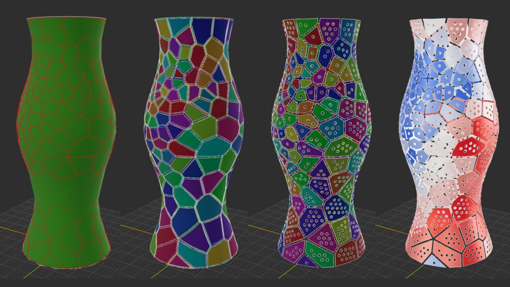
| Test model | A vase: 240 panels, 761 holes, 14 part types |
Why I built the Panelization plugin
While I work on a design, I think about fabrication at the same time: how it will be made, in what material and with which method. Even before that, I think about how the geometry will be divided. The way a form is split into pieces is what makes it fabrication-friendly and, at the same time, affordable to build.
Recently I was working on a new project in BeeGraphy and asked myself a simple question: what if I actually had to fabricate this and turn it into a real, tangible object? That question became the Panelization plugin.
I wrote down the rules a fabricator would give me. Panels are cut on a laser or CNC from 4 × 8 ft sheets, so anything that overlaps or hangs off a sheet is waste. Every panel should land between roughly 150 and 300 mm, so small panels are resized into that range instead of being merged into their neighbors. Each part needs a number in its middle so the form can be put back together. Anything that adds material or waste, like perforation or a frame, has to stay optional.
How the panelization graph is organized
The 12 nodes sit in five groups, in the order you use them: Input, Patterns, Optimize, Panels and Fabrication. The main chain runs straight through, from Shell Faces to Sheet Report. The checking nodes branch off it, so you can add them when you need them and leave the graph lean when you don’t.
Every step ends in geometry you can preview, so you always see what the last node did before you add the next one.
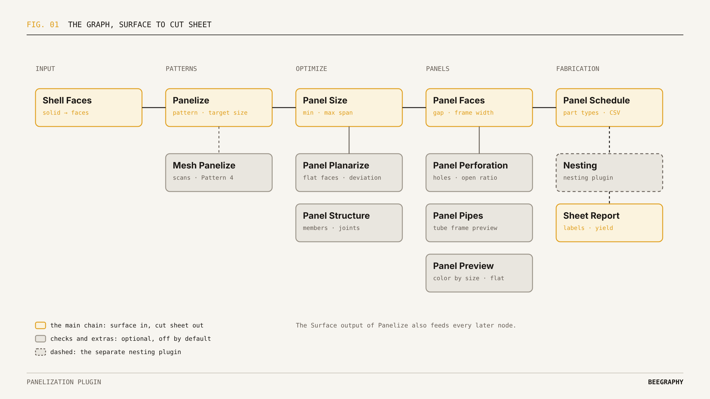
Fig. 01 · The graph in five groups. Amber: the main chain. Grey: optional checks and extras. Dashed: the separate nesting plugin.
01 · Input: one face at a time
Shell Faces splits a solid or a multi-face surface into its faces. Every later node then works face by face, so panels stop exactly on the face edges instead of wrapping around a corner. For a vase or a building standing on the ground, Skip Bottom leaves out the flat base.
02 · Patterns: deciding how the surface divides
Panelize is the core of the panelization workflow. It divides the surface with one of four patterns: Voronoi, UV grid, triangulation or hexagonal. Target Size sets the panel span in model units and is the main density control. Seed and Relax Iterations reshape the cells, and attractor points make panels smaller where you want more detail.
For scans and imported models, Mesh Panelize grows even regions over the mesh and passes them to Panelize as a fifth pattern.
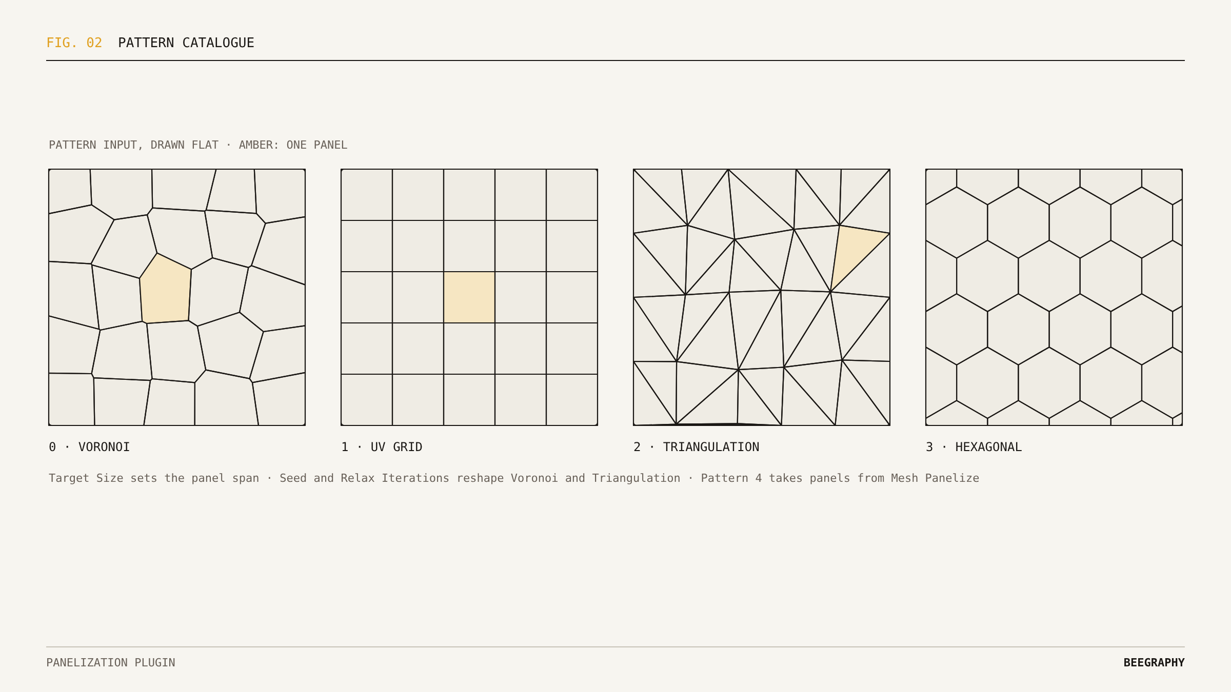
Fig. 02 · The four patterns of Panelize, drawn flat. One panel in each is highlighted in amber.
03 · Optimize: panels you can actually make
A pattern that looks good is not yet a set of parts. Panel Size keeps every panel between a minimum and a maximum span. Panels that are too big are split. Panels that are too small grow by pushing their shared corners outward along the surface, but only into neighbors that are themselves big enough. Nothing is merged, so the pattern keeps its character.
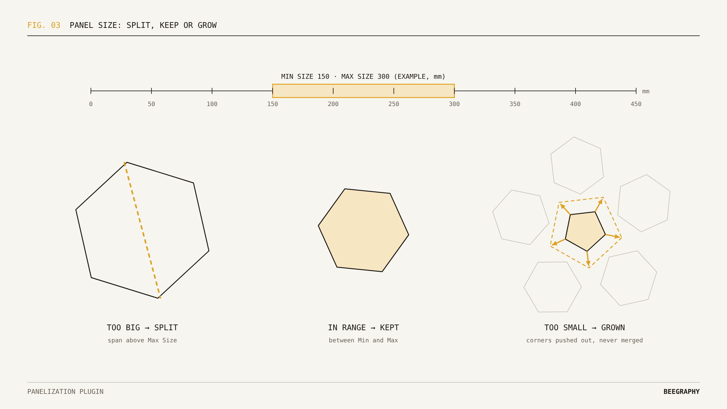
Fig. 03 · Panel Size with an example range of 150 to 300 mm. Big panels are split, small ones grow into their neighbors, and nothing is merged.
Two more nodes check what you will build. Panel Planarize moves corners so panels become flat while neighbors still share corners, and it reports how far each panel is from flat. Its Planar Faces are always exactly flat and ready to cut. Panel Structure finds one frame member per shared edge, flags members that are too short to make, and counts how many different lengths and joint angles you need.
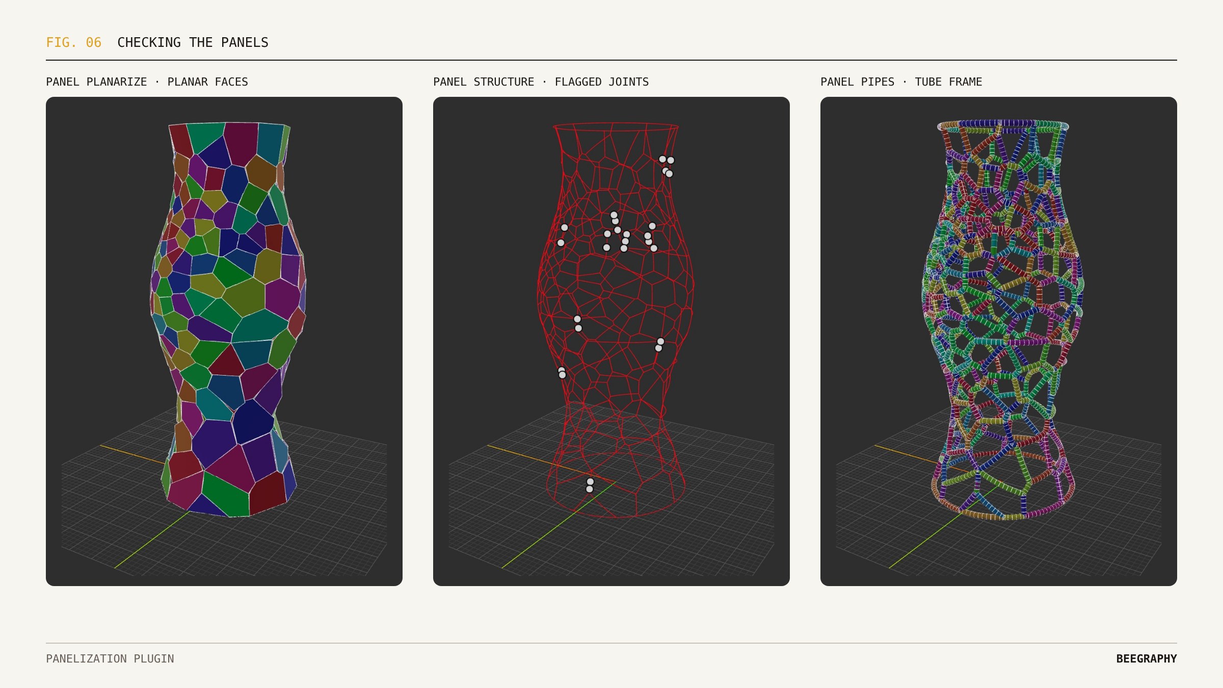
Fig. 06 · Checking the panels: exactly flat Planar Faces, flagged joints from Panel Structure, and a tube frame preview from Panel Pipes.
04 · Panels: faces, frames and holes
Panel Faces turns outlines into real geometry. Gap shrinks the panels so neighbors sit a set distance apart. Frame Width adds a mitered border inside every panel. Flat panels are filled directly; curved panels are cut from the surface so neighbors still meet cleanly.
Panel Perforation adds round holes, kept away from the edge by a margin and graded by attractor points. On the test vase it cut 761 holes. Panel Pipes previews a frame as tubes and joints, and Panel Preview colors every panel by size, flatness or part type so problem areas stand out.
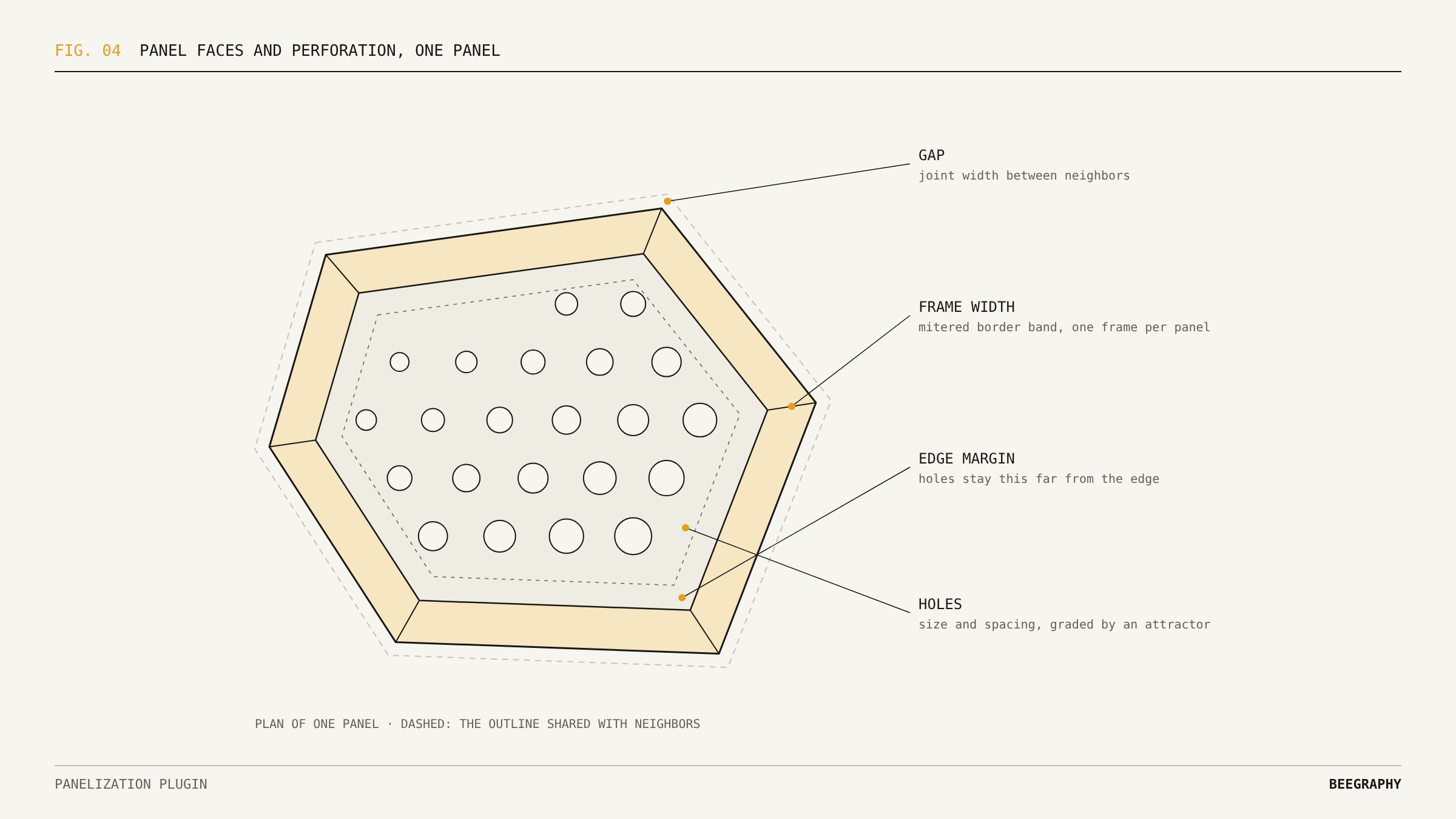
Fig. 04 · One panel in plan. The gap separates neighbors, the frame is a mitered band, and the holes keep an edge margin.
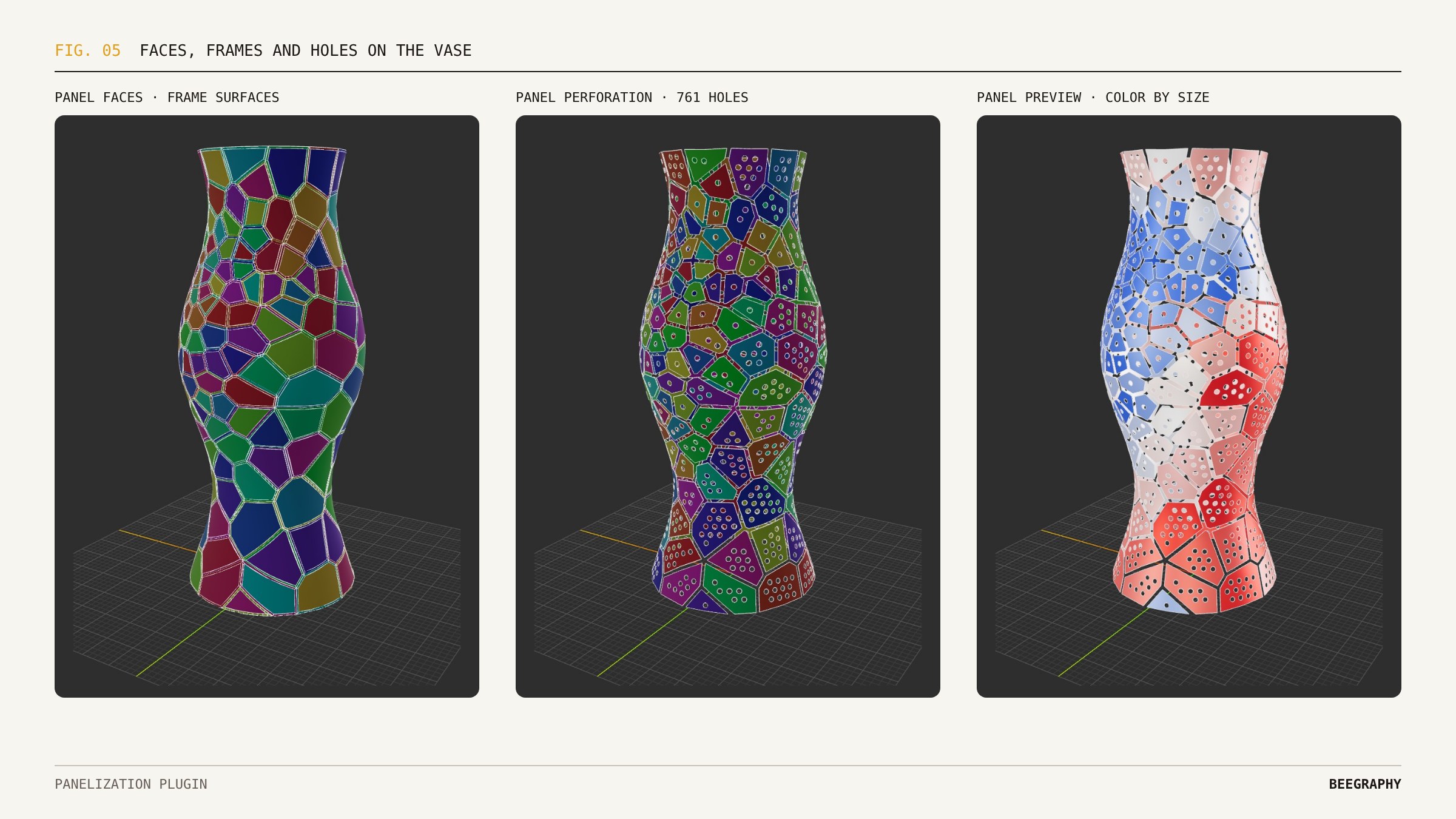
Fig. 05 · The same vase after Panel Faces, Panel Perforation (761 holes) and Panel Preview colored by size.
05 · Fabrication: from panels to a labeled cut sheet
Panel Schedule groups panels with the same flat shape into part types, writes one row per panel to a table and CSV, and unrolls every panel flat. On the vase, 240 panels came down to 14 part types. Its flat outlines go to a nesting node, which places them on your sheets.
Sheet Report reads the nesting result. With a Font node connected, it draws each part’s number as engraving text, centered in the part and shrunk until it stays inside the outline. It also reports the sheets used, the yield, the cost and a cutting check that warns about overlapping parts or parts over the sheet edge.
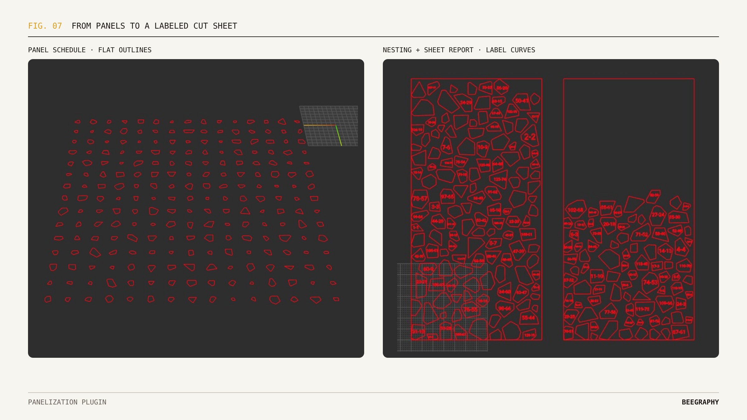
Fig. 07 · Left: every panel laid flat by Panel Schedule. Right: the panels nested on sheets with their numbers from Sheet Report. The sheets are scaled down here to suit the small demo vase.
Surface in, cut sheet out
- Input: split the solid into faces with Shell Faces.
- Pattern: divide each face with Panelize and set the target size.
- Size: keep every panel in range with Panel Size.
- Check: flatten and measure with Panel Planarize, and check members with Panel Structure.
- Build: make faces, frames and holes with Panel Faces and Panel Perforation.
- Schedule: group part types and lay the panels flat with Panel Schedule.
- Nest and label: place the parts on sheets and engrave their numbers with Sheet Report.
Because every step is a node with sliders, you can change the pattern or the panel size and the whole chain, down to the labels on the cut sheet, updates with it.
Try the Panelization plugin
Add Panelization to your BeeGraphy workspace, drop a surface into Shell Faces and work down the chain. The Panelization guide in the help center walks through every node, input and output with screenshots, and the Nesting guide covers the sheet layout step.
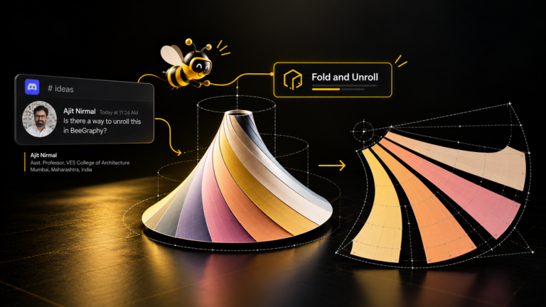
If you want to see how a community idea becomes a plugin, read how we built Fold and Unroll.
Frequently asked questions
What is panelization in design and architecture?
Panelization is the process of dividing a surface into smaller panels that can be manufactured, transported and assembled. In BeeGraphy, the Panelization plugin does this with nodes, from the pattern all the way to labeled cut sheets.
Which panel patterns does the plugin support?
Panelize supports Voronoi, UV grid, triangulation and hexagonal patterns, plus mesh panels from Mesh Panelize for scans and imported models.
Do the panels have to be flat?
No. Curved panels are cut from the surface. If you need flat parts for sheet cutting, Panel Planarize gives you exactly flat faces and shows how far each panel was from flat.
Which machines is it made for?
It is set up for sheet cutting on a laser or CNC router. Panel Schedule lays the parts flat, a nesting node places them on sheets, and Sheet Report checks the layout and adds engraving labels.
More plugin stories and build breakdowns are on the BeeGraphy blog.