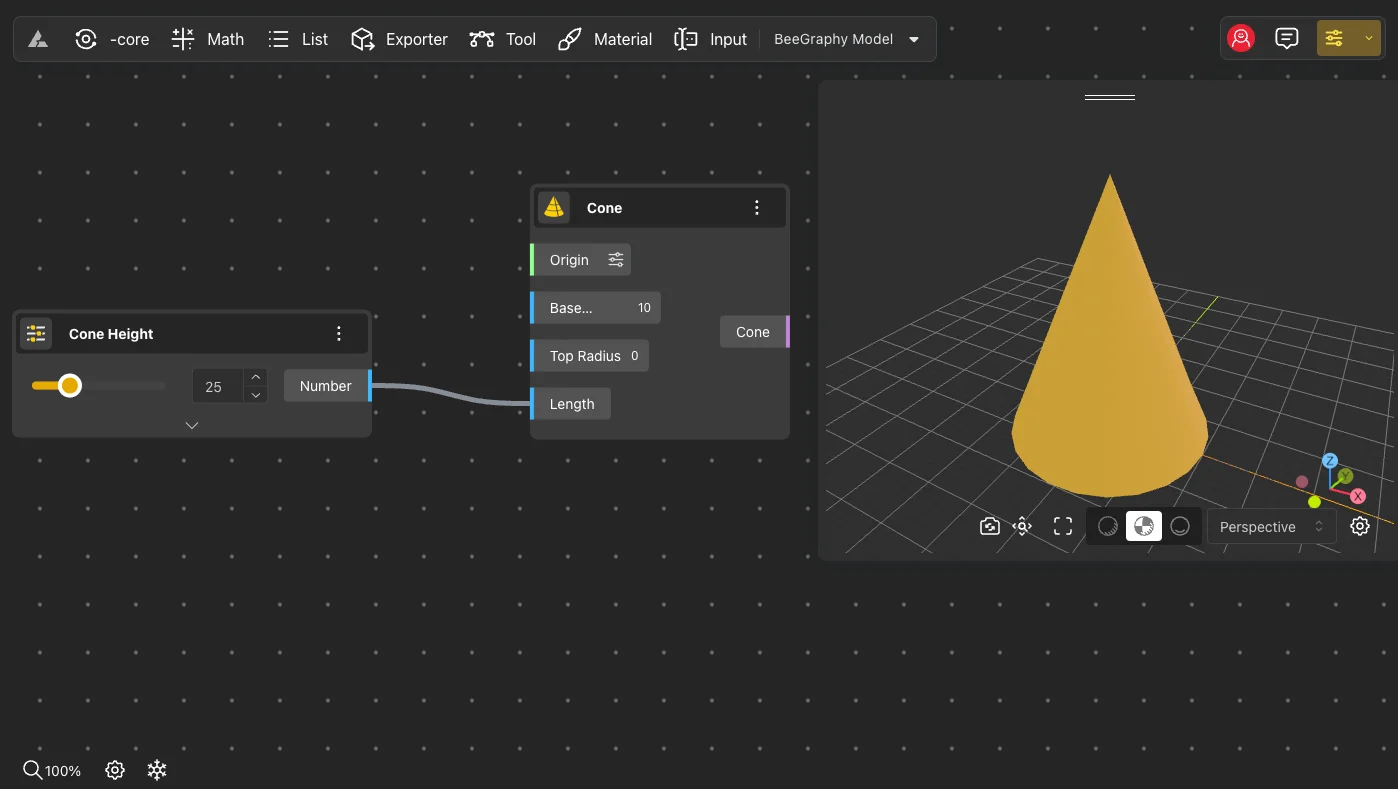
Another component of the Editor is the 3D view.
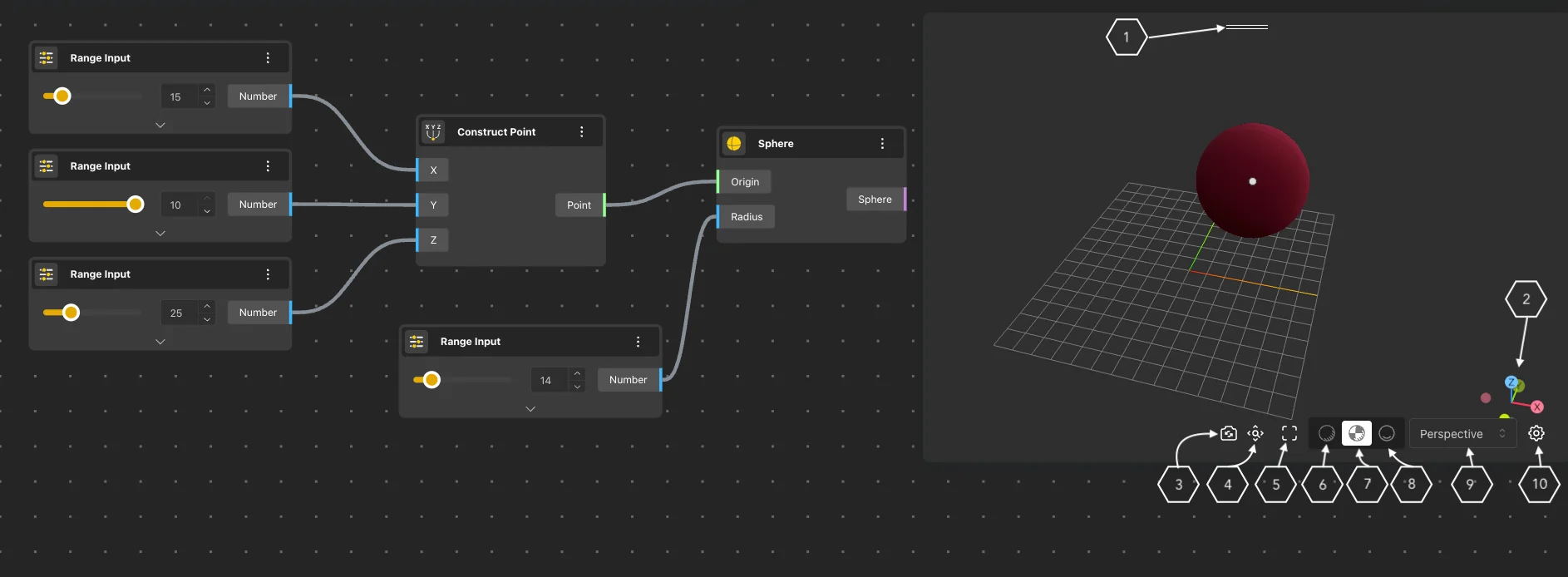
On the right side of the workspace is the 3D view, which can be adjusted by dragging any of the other three cells from the window’s transport zone (1) as desired. Here, you can observe the associated values of the nodes placed in the workspace, as well as the rendered output values displayed in 3D space.
The mouse scroll button is used for zooming in or out view of the geometry.
To view the geometry from different angles, use the left mouse button to rotate the geometry in any direction.
Adjust the viewing position of the geometry by holding down the right mouse button and moving in different directions.
To resize the 3D view, hold down the left mouse button and adjust the size in the desired direction.
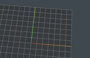
In the right corner, you can see the XYZ coordinate axes directions (2).
Other 3D view management tools include:
Model position save button (3): This feature allows you to lock the geometry’s position from a desired angle and display it in Viewer Mode or Market with that position.
The Zoom to Fit (4) button serves multiple functions: when a node is selected and this button is clicked, the geometry of the selected node is displayed. Without selecting any node, clicking this button displays all geometries.
Press the Full Screen (5) button to view the geometry in its entirety. To exit this mode, press the same button again.
There are several modes of geometry reflection:
In Shaded (6) mode, the model is displayed with lightweight shading, consuming less computer memory. Different colors represent surfaces.
Rendered (7) mode provides better quality and materialized geometry display.
In Shadow (8) mode, you can work with the glow of the geometry, which has two sub modes.
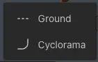
Ground - illuminates the floor.
Cyclorama - illuminates the cyclorama.
Used to change the viewing directions of the geometry.
Perspective (9) button: Opens a menu where you can select from the following options:
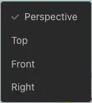
Perspective: Provides a view from different directions.
Top: Provides a view from above.
Front: Provides a view from the front.
Right: Provides a view from the right.
Selecting elements from viewer
You can select elements in the viewer, and the node that shows this element will also be selected.
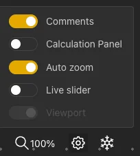
If the Auto Zoom function in the lower left corner is turned on, the node will be zoomed in
Other 3D View Settings (10)
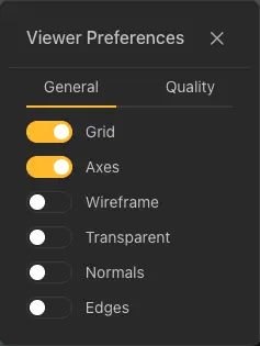
Grid - enables or disables grid display.
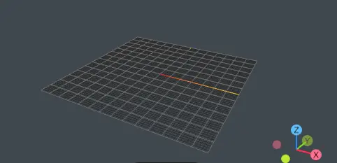
Axes - turn on or off the display of X, Y axes
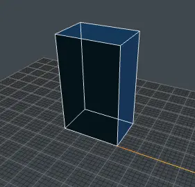
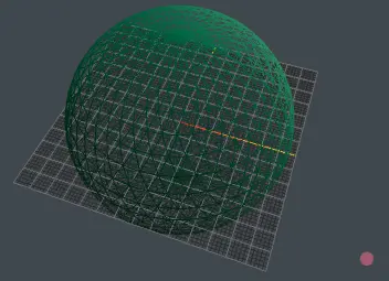
Wireframe - displays the geometry in mesh form.
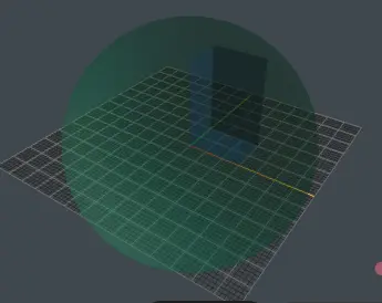
Transparent - makes the geometry transparent
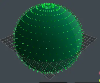
Normals - displays the directions of geometry normals.
Edges - displays geometry borders.