The Primitive Curves group is designed for generating geometrically simple, linear shapes.
Line
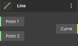
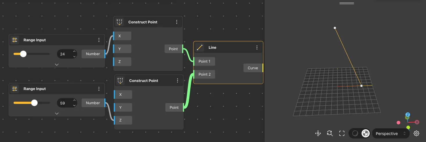
The Line node generates a line segment between the start and end points provided in the node’s input. The resulting line is shown in the view.
Node usages
Polyline
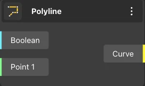
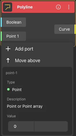
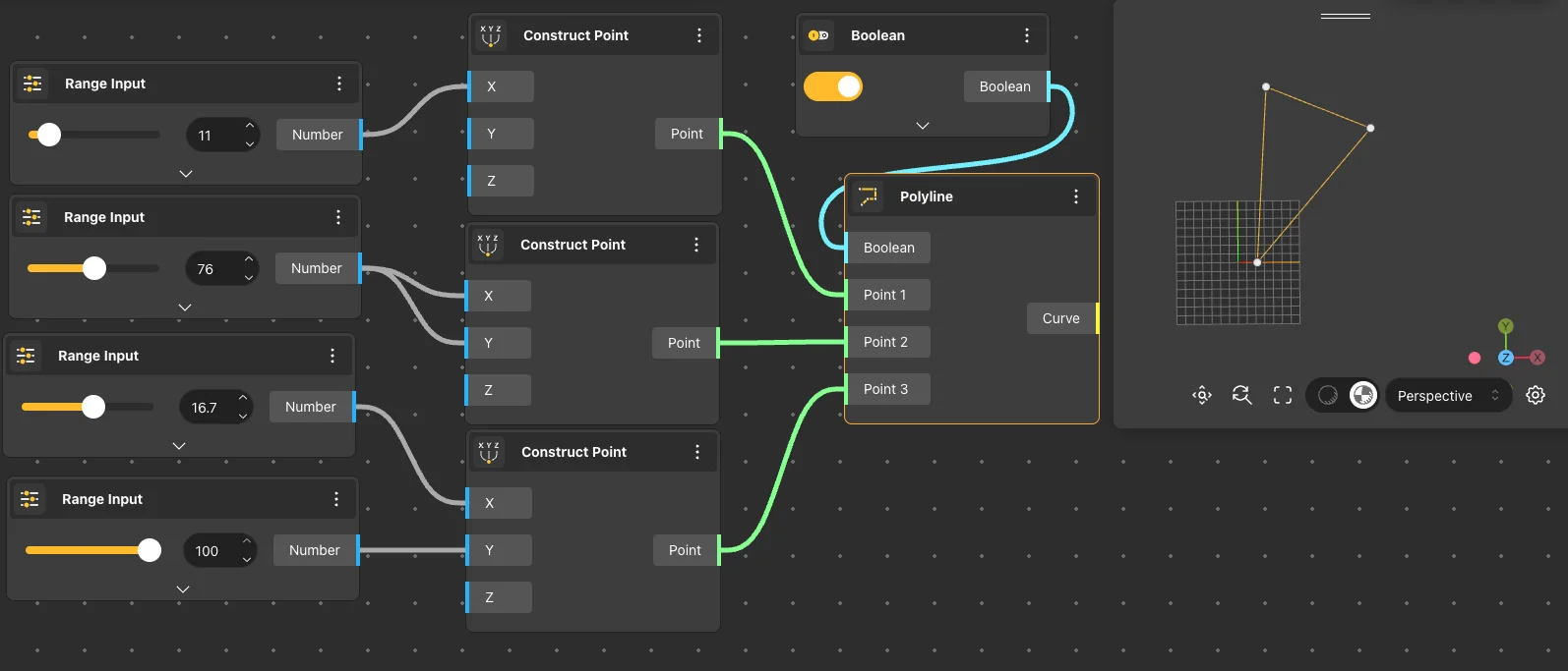
A Polyline node returns a polyline formed by connecting the points provided in the node’s input. Additional points can be added using the ’add port’ command of the node. The other input of the node accepts a boolean value; if true, the polyline will be closed, and if false, it will remain open. The Polyline node is shown resulting polyline in the view.
Additional points can be added using the ’add port’ command of the node.
Node usages
Interpolate
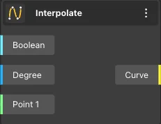
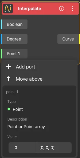
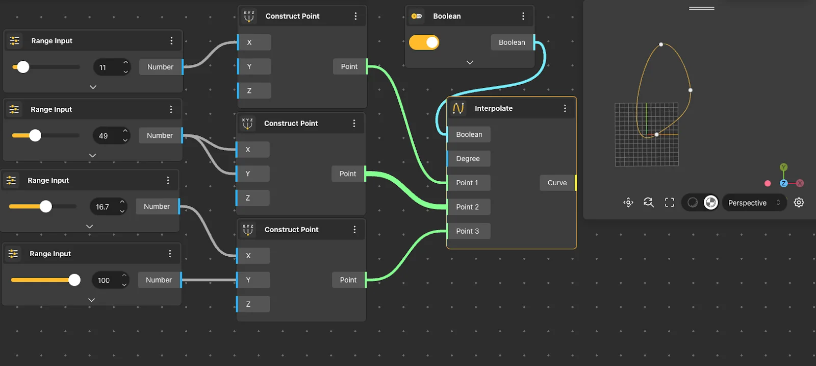
The Interpolate node receives points or an array of points as input and generates an interpolated curve passing through those points. Additionally, it can receive input from other nodes to determine the degree of the curve and whether the resulting curve is closed or open.
Additional points can be added using the ’add port’ command of the node.
Node usages
NURBS Curve
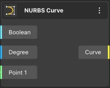
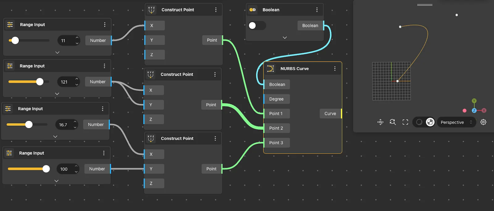
The NURBS Curve node receives points or an array of points as input and generates a NURBS curve constructed from those points. It can also receive input from other nodes to specify the degree of the curve and whether the resulting curve is closed or open.
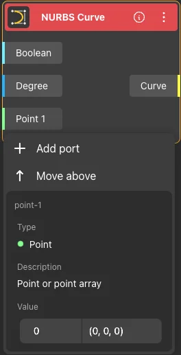
Additional points can be added using the ’add port’ command of the node.
Node usages
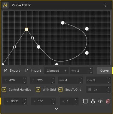
Curve Editor
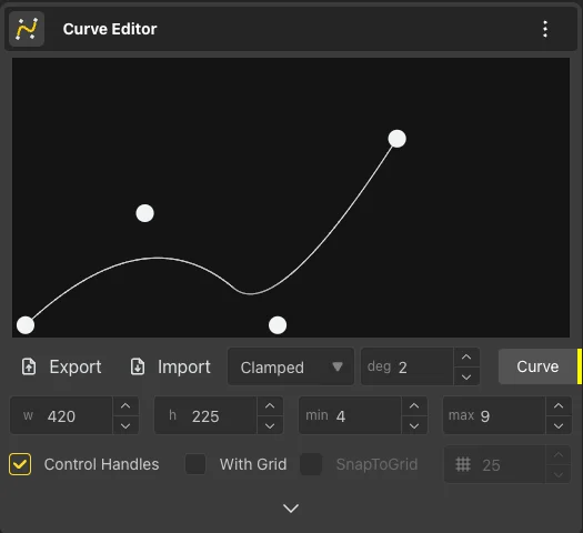
The Curve Editor node returns a NURBS curve using the control points, degree, and curve type provided in the node’s input field. Double-clicking on the input field allows for the addition of a new control point. Subsequently, the Curve Editor node shows the resulting curve in the View.
Node usages
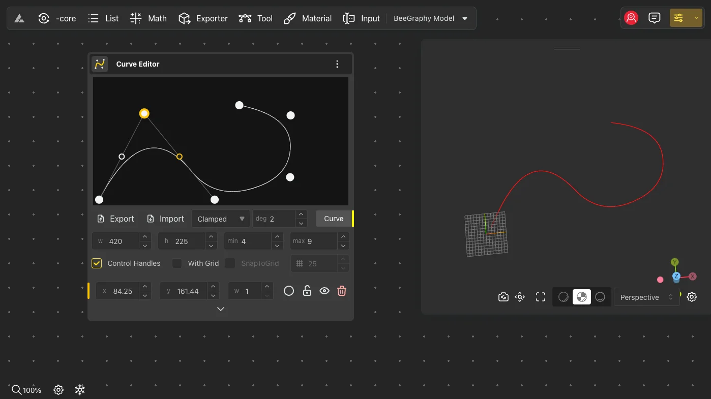
To insert a control point between existing points, click on the position immediately before or after where you want the new point to be added. This will cause two small points to appear. Then, by double-clicking on one of these small points, a new control point will be inserted at that location.
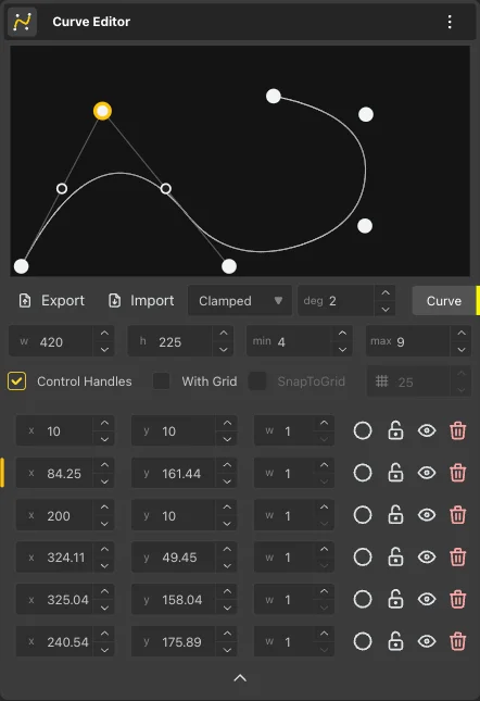
To change a point from smooth to sharp, click on the circle next to the point in the point list menu; this will turn the point into a sharp one. Conversely, to change a sharp point to a smooth one, click on the rectangle in the same menu.
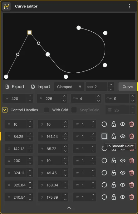
Additionally, you have the option to add a grid to the editor. You can adjust the grid size to your preference and enable snapping to align points precisely with the grid lines.
Circle
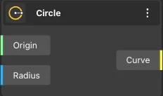
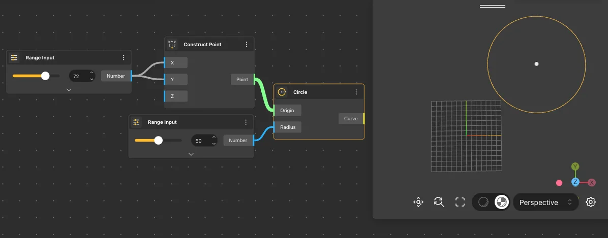
The Circle node generates a circle with the center and radius specified in the node’s input. Subsequently, the Circle node shows the resulting circle in the View.
Node usages
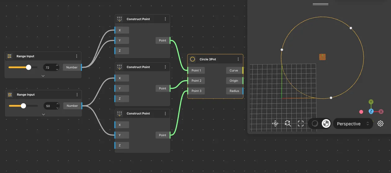
Circle 3Pnt
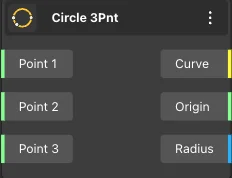
The Circle 3Pnt node returns a circle that passes through the three points provided in the node’s input. Subsequently, the Circle 3Pnt node shows the resulting circle in the View.
Node usages
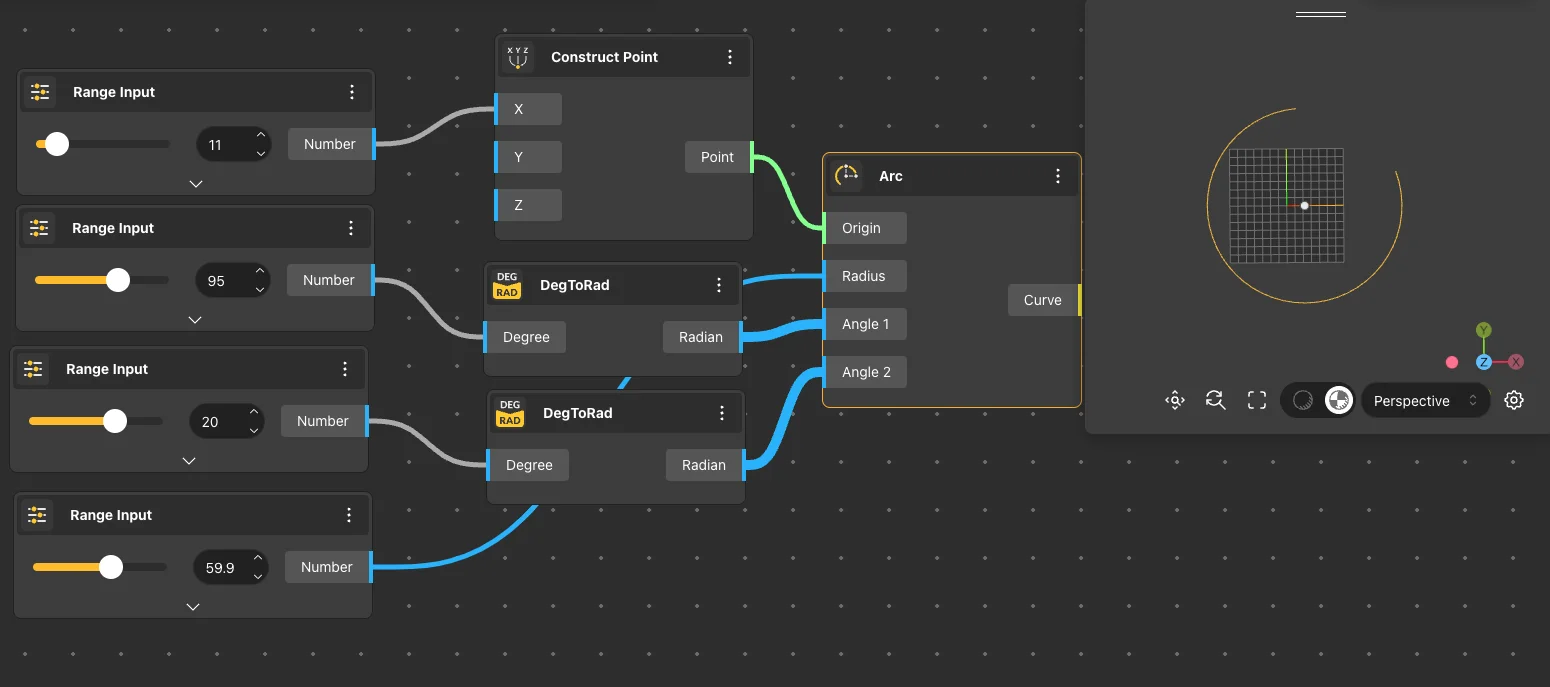
Arc
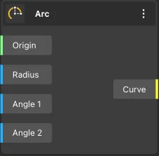
The Arc node returns an arc with its center and radius determined by the values provided in the node’s input. Additionally, the initial and final angles of the arc are obtained through other nodes.
Node usages
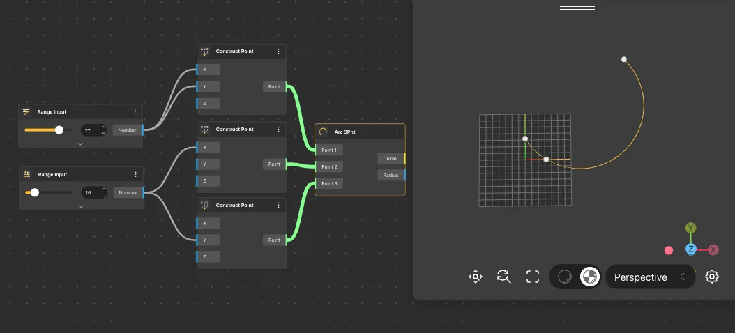
Arc 3Pnt
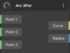
The Arc 3Pnt node returns an arc that passes through the three points provided in the node’s input. Subsequently, the Arc 3Pnt node shows the resulting arc in the View.
Node usages
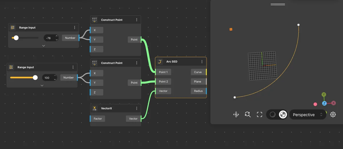
Arc SED
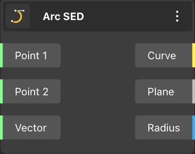
The Arc SED node returns an arc constructed with the start and end points provided in the input. The direction of the arc is determined by the vector given by the third node. Subsequently, the Arc SED node shows the resulting arc in the View.
Node usages
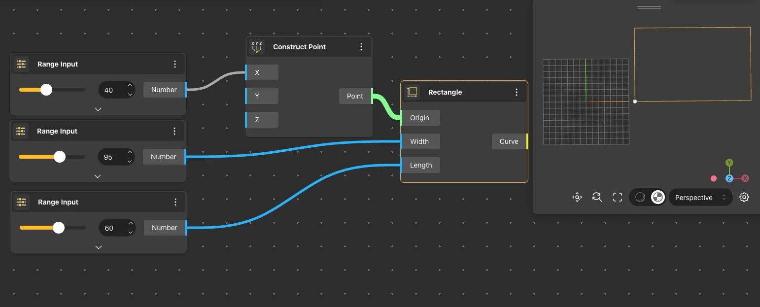
Rectangle
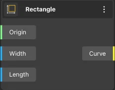
The Rectangle node returns a rectangle whose origin and dimensions are specified by the values provided in the node’s input. Subsequently, the Rectangle node shows the resulting rectangle in the View.
Node usages
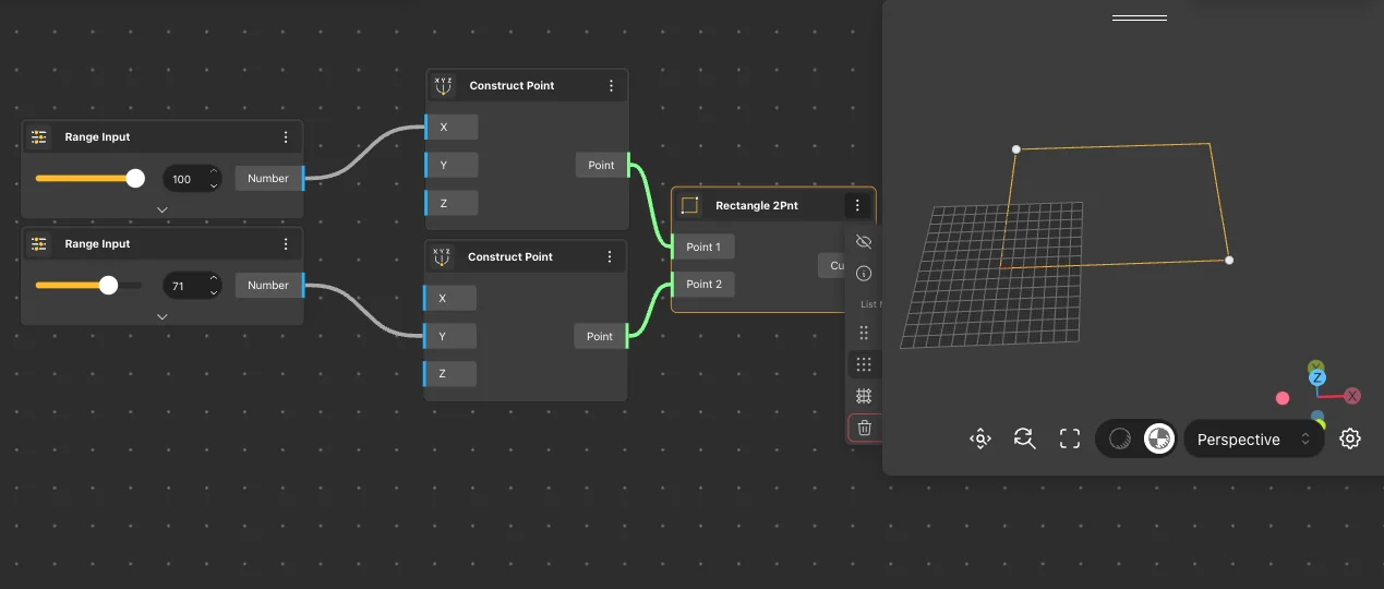
Rectangle 2Pnt
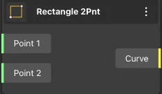
The Rectangle 2Pnt node returns a rectangle constructed with its diagonal endpoints specified by the values provided in the node’s input. Subsequently, the Rectangle 2Pnt node represents the resulting rectangle on the View.
Node usages
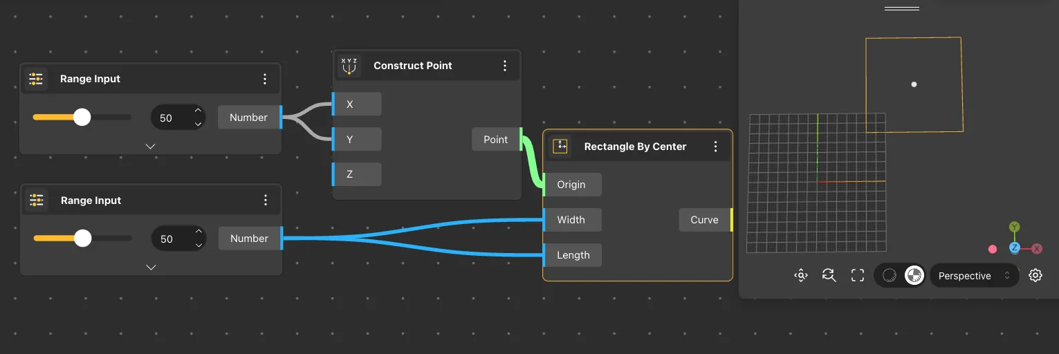
Rectangle By Center
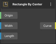
The Rectangle By Center node returns a rectangle with its center and dimensions specified by the values provided in the node’s input. Subsequently, the Rectangle By Center node represents the resulting rectangle on the View.
Node usages
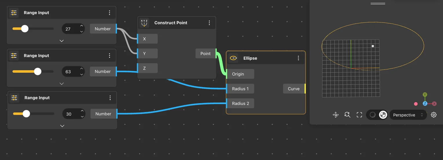
Ellipse
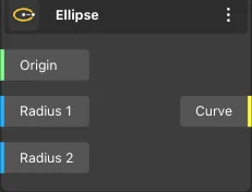
The Ellipse node returns an ellipse with its center and two radii specified by the values provided in the node’s input. Subsequently, the Ellipse node represents the resulting ellipse on the View.
Node usages
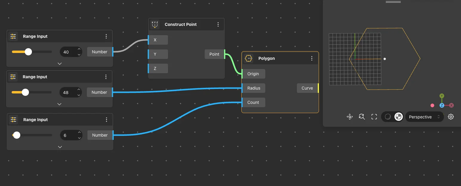
Polygon
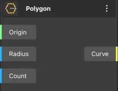
The Polygon node returns a polygon with its center, radius, and number of sides specified by the values provided in the node’s input. Subsequently, the Polygon node shows the resulting polygon in the View.
Node usages
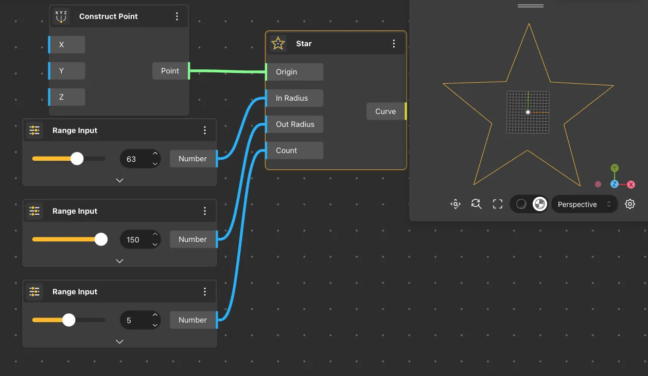
Star
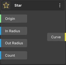
The Star node returns a star-shaped polygon with its inner and outer radii, as well as the number of vertices, specified by the values provided in the node’s input. Subsequently, the Star node shows the resulting star-shaped polygon in the View.
Node usages
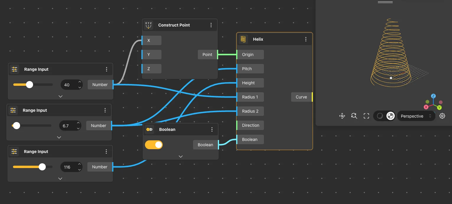
Helix
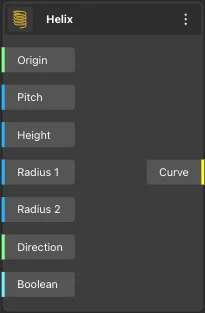
The Helix node returns a spiral, with input nodes allowing control over the center point of the base of the spiral, step size, height, lower and upper radii, orientation, and rotation direction of the spiral.
Node usages